Sony slv ks 1 service manual

This is the 44 pages manual for sony slv ks 1 service manual.
Read or download the pdf for free. If you want to contribute, please upload pdfs to audioservicemanuals.wetransfer.com.

Page: 1 / 44
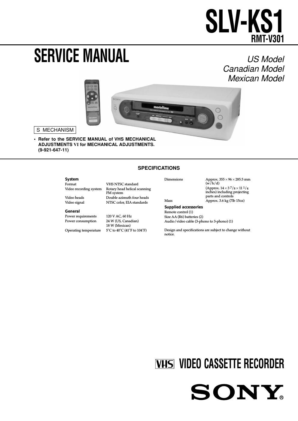
sony slv ks 1 service manual

Extracted text from sony slv ks 1 service manual (Ocr-read)


Page 2

– 3 – TABLE OF CONTENTS Section Title Page Section Title Page SERVICE NOTE ...................................................................... 4 1. GENERAL Play Timer ...................................................................... 1-1 Cassette Door Lock (Safety Lock) ................................ 1-1 Recording and Tape Speed Buttons ............................. 1-1 Connections .................................................................. 1-2 2. DISASSEMBLY 2-1. Upper Case Removal.................................................... 2-1 2-2. Front Panel Section Removal....................................... 2-1 2-3. Rear Panel (M) Removal.............................................. 2-1 2-4. Mechanism Deck Removal........................................... 2-1 2-5. MA-370 Board Removal................................................ 2-2 2-6. Internal Views................................................................ 2-3 2-7. Circuit Boards Location................................................. 2-4 3. BLOCK DIAGRAMS 3-1. Overall Block Diagram.................................................. 3-1 3-2. Video Block Diagram..................................................... 3-3 3-3. Servo/System Control Block Diagram.......................... 3-5 3-4. Audio Block Diagram..................................................... 3-7 3-5. Power Block Diagram.................................................... 3-9 4. PRINTED WIRING BOARDS AND SCHEMATIC DIAGRAMS 4-1. Frame Schematic Diagram........................................... 4-3 4-2. Printed Wiring Boards and Schematic Diagrams......... 4-5 MA-370 Printed Wiring Board ....................................... 4-5 MA-370 (Head Amp) Schematic Diagram .................... 4-7 MA-370 (Video, Audio) Schematic Diagram ................. 4-9 MA-370 (Servo/System Control) Schematic Diagram ....................................................... 4-13 MA-370/QP-1 (Kids Sound) Printed Wiring Board and Schematic Diagram ................................................ 4-17 MA-370 (Mode Control) Schematic Diagram ............... 4-19 MA-370 (Power Supply) Schematic Diagram ............... 4-21 5. INTERFACE, IC PIN FUNCTION DESCRIPTION 5-1. System Control-Video/RP Block Interface (MA-370 BOARD IC160) ............................................... 5-1 5-2. System Control-Servo Peripheral Circuit Interface (MA-370 BOARD IC160) ............................................... 5-1 5-3. System Control-Mechanism Block Interface (MA-370 BOARD IC160) ............................................... 5-2 5-4. System Control-System Control Peripheral Circuit Interface (MA-370 BOARD IC160) .................... 5-3 5-5. System Control-Audio Block Interface (MA-370 BOARD IC160) ............................................... 5-3 5-6. Servo/System Control Microprocessor Pin Function (MA-370 BOARD IC160) ............................................... 5-4 6. ADJUSTMENTS 6-1. Mechanical Adjustments............................................... 6-1 6-2. Electrical Adjustments................................................... 6-1 2-1. Pre-Adjustment Preparations........................................ 6-1 2-1-1. Instruments to be Used ............................................ 6-1 2-1-2. Connection............................................................... 6-1 2-1-3. Set-up of Adjustment ................................................ 6-1 2-1-4. Alignment Tapes ....................................................... 6-1 2-1-5. Specified I/O Level and Impedance input/output terminal ................................................ 6-1 2-1-6. Adjusting Sequence ................................................. 6-2 2-2. Power Supply Adjustment............................................. 6-2 2-2-1. Power Supply Check ................................................ 6-2 2-3. Servo System Adjustment............................................. 6-2 2-3-1. RF Switching Position Adjustment ........................... 6-2 2-4. Audio System Adjustments........................................... 6-3 2-4-1. Normal Audio System Adjustment ........................... 6-3 1. ACE Head Adjustment .................................................. 6-3 2. E-E Output Level Check ............................................... 6-3 3. Frequency Response Check ......................................... 6-3 2-5. Parts Arrangement Diagram for Adjustments............... 6-4 7. REPAIR PARTS LIST 7-1. Exploded Views............................................................. 7-1 7-1-1. Front Panel and Chassis Assembly ......................... 7-1 7-1-2. Mechanism Chassis Assembly (1) ........................... 7-2 7-1-3. Mechanism Chassis Assembly (2) ........................... 7-3 7-1-4. Mechanism Chassis Assembly (3) ........................... 7-4 7-2. Electrical Parts List........................................................ 7-5