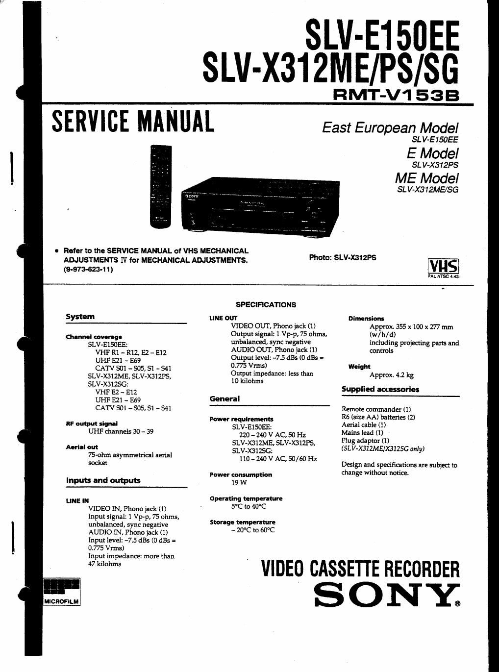
Sony slv e 150 ee service manual
This is the 93 pages manual for sony slv e 150 ee service manual.
Read or download the pdf for free. If you want to contribute, please upload pdfs to audioservicemanuals.wetransfer.com.
Extracted text from sony slv e 150 ee service manual (Ocr-read)
Page 2
Section
TABLE OF CONTENTS
Title
SERVICE NOTE ...................................
OPC (OPTIMUM PICTURE CONTROL) CIRCUIT
1.
2-1.
2-2.
2-3.
2-4.
2-5
3-1.
3-2.
3-3,
34.
3A5,
3-6.
3-7,
4-1 t
4-2.
General
Record Mode
Playback Mode -----------------
GENERAL
Index to Parts and Controls
Introduction
Getting Started -- -
Basic Operations - -
Additional Operations ---------
DISASSEMBLY
Front Panel Assembly and Case -----
Vl-134 Board and MD Assembly
MA212 and PS-SSB Boards
Internal Views
Circuit Boards Location
BLOCK DIAGRAMS
Overall Block Diagram - -
Video Block Diagram """
Servo. system Control Block Diagram
Audio Block Diagram ------
Tuner Block Diagram .
Mode Control Block Diagram -
Power Supply Block Diagram
PRINTED WIRING BOARDS AND
SCHEMATIC DIAGRAMS
Frame Schematic Diagram
Primed Wiring Boards and Schematic Diagrams
Vl~134 (Head Amp. Video) Board ----------------
MA-212 (Servo System Control Normal Audio)
Board ~
MA-212 (Made Control), SW-241 (Switches)
Boards
F's-338 (Power Supply) Board
- 1-1
1-2
1<2
1-7
lg
(D
1-12
- 2-1
- 2~2
. 2-2
- 2-3
. 24
' 3-1
34
3-7
- 3~10
- 3-10
- 3-12
' 3-13
- 4-1
~ 44
4-4
4'13
- 4-21
Section 772i Page
5. REPAIR PARTS LIST
5'1. Exploded Views -------------------------------- 5-1
Front Panel Assembly ------------------- -~ 5-1
chassis .................. . . 5.2
Mechanism Deck Assembly (1) - -~ 5-3
Mechanism Deck Assembly (2) 54
Mechanism Deck Assembly (3) 5-5
5-1-6. Mechanism DeckAsserany (4) - ~ 5-6
52. Electrical Parts List ------------- - 54
Hardware List .................................. 5,1 5
6. INTERFACE. IC PIN FUNCTION DESCRIPTION
6-1. System Control - Mechanism Block Interface ------ 6-1
6-2. System Control - Servo Peripheral Circuit
Interface ....................................... 6.2
6-3. System Control - System Control Peripheral
Circuit Interface -------- - ------------------- 6-3
6-4, System Control - Input Selection Block Interface ~' 6-3
6-5. System Control - Video Block Interface ------- - ~ 63
664 System Control - Audio Block Interface ~~~~~~ 6-3
5-7. Servo. System Control Microprocessor
Pin Function ................... . ............... 5.4
6-8. LCD Driver Pin Function ------------------------ 6-5
7. ADJUSTMENTS
7-1. Mechanical Adjustments -------------------- w - - - 74
7-2 Electrical Adfustments -» 7-1
2-1t (re-Adjustment Preparations ~ 7-1
2-1-1. Instruments to be Used ~ - 7-1
24-2 Connection ~~~~~~~~~~~~~~~~ 7~1
2-1-3. Set-up of Adiustment 74
2-1 -4. Alignment Tape --------------- ~ 74
24-5 Specified [/0 Level and Impedance - -~ 72
24-6. Adiusting Sequence ------------ - 7-2
2-2. Power Supply Check ---------- H 7-2
2-3. ServoNideo System Adjustments .. 7-2
2~3-i. Switching Position Adjustment ------------- 7-2
2-3 SECAM Discrimination Adjustment --------- 7-3
2-3-3. V00 Frequency Adiustment ----- .. 7-3
2-4. Audio System Adjustments ---------- -- 7<3
24-1. Normal Audio System Adiustments ~- 7<3
2-5. Pans Arrangement Diagram for Adjustments ----- 7-4