Sony slv d 360 p service manual

This is the 123 pages manual for sony slv d 360 p service manual.
Read or download the pdf for free. If you want to contribute, please upload pdfs to audioservicemanuals.wetransfer.com.

Page: 1 / 123
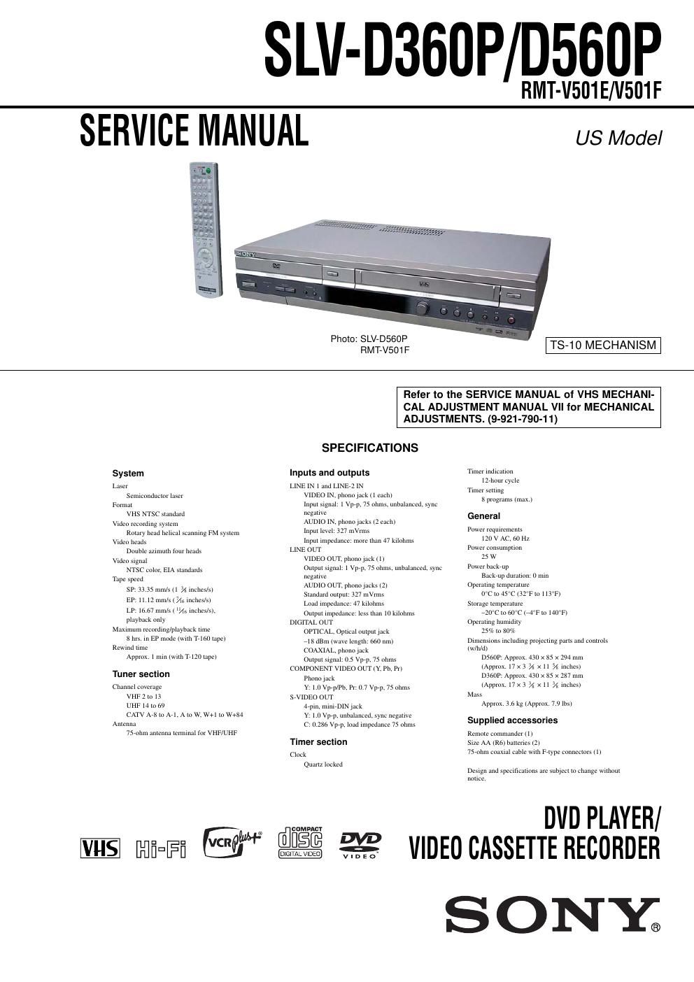
sony slv d 360 p service manual

Extracted text from sony slv d 360 p service manual (Ocr-read)


Page 1

- 2 - WARNING!! WHEN SERVICING, DO NOT APPROACH THE LASER EXIT WITH THE EYE TOO CLOSELY. IN CASE IT IS NECESSARY TO CONFIRM LASER BEAM EMISSION, BE SURE TO OBSERVE FROM A DISTANCE OF MORE THAN 25 cm FROM THE SURFACE OF THE OBJECTIVE LENS ON THE OPTICAL PICK-UP BLOCK.CAUTION Use of controls or adjustments or performance of procedures other than those specified herein may result in hazardous radiation exposure. SAFETY-RELATED COMPONENT WARNING!! COMPONENTS IDENTIFIED BY MARK 0 OR DOTTED LINE WITH MARK 0 ON THE SCHEMATIC DIAGRAMS AND IN THE PARTS LIST ARE CRITICAL TO SAFE OPERATION. REPLACE THESE COMPONENTS WITH SONY PARTS WHOSE PART NUMBERS APPEAR AS SHOWN IN THIS MANUAL OR IN SUPPLEMENTS PUBLISHED BY SONY. CAUTION: The use of optical instrument with this product will increase eye hazard. Fig. A. Using an AC voltmeter to check AC leakage. 1.5 k Ω 0.15 µF AC voltmeter (0.75 V) To Exposed Metal Parts on Set Earth Ground LEAKAGE TEST The AC leakage from any exposed metal part to earth ground and from all exposed metal parts to any exposed metal part having a return to chassis, must not exceed 0.5 mA (500 microamperes). Leakage current can be measured by any one of three methods. 1. A commercial leakage tester, such as the Simpson 229 or RCA WT-540A. Follow the manufacturers' instructions to use these instruments. 2. A battery-operated AC milliammeter. The Data Precision 245 digital multimeter is suitable for this job. 3.Measuring the voltage drop across a resistor by means of a VOM or battery-operated AC voltmeter. The limit indication is 0.75V, so analog meters must have an accurate low-voltage scale. The Simpson 250 and Sanwa SH-63Trd are examples of a passive VOM that is suitable. Nearly all battery operated digital multimeters that have a 2V AC range are suitable. (See Fig. A) 1. Check the area of your repair for unsoldered or poorly-soldered connections. Check the entire board surface for solder splashes and bridges. 2.Check the interboard wiring to ensure that no wires are pinched or contact high-wattage resistors. 3.Look for unauthorized replacement parts, particularly transistors, that were installed during a previous repair. Point them out to the customer and recommend their replacement. 4. Look for parts which, though functioning, show obvious signs of deterioration. Point them out to the customer and recommend their replacement. 5. Check the line cord for cracks and abrasion. Recommend the replacement of any such line cord to the customer. 6. Check the B+ voltage to see it is at the values specified. 7. Check the antenna terminals, metal trim, metallized knobs, screws, and all other exposed metal parts for AC leakage. Check leakage as described below. SAFETY CHECK-OUT After correcting the original service problem, perform the following safety checks before releasing the set to the customer:

Page 2

- 3 - TABLE OF CONTENTS Precautions 1Safety Precautions ······························································ 4 2Servicing Precautions ························································ 6 3ESD Precautions ································································· 7 4Handling the Optical Pick-up ············································· 8 5Pick-up Disassembly and Reassembly ······························ 9 1. General Getting Started ································································· 1-1 Basic Operations ······························································ 1-7 Advanced Hookups ······················································· 1-15 DVD Settings and Adjustments ····································· 1-16 DVD Additional Operations ·········································· 1-18 VCR Additional Operations ·········································· 1-24 Additional Information ·················································· 1-27 2. Disassembly and Reassembly 2-1 Cabinet and PCB 2-1-1 Cabinet Top Removal ····················································· 2-1 2-1-2 Bottom Cover Removal ·················································· 2-1 2-1-3 Assy Front Panel Removal ············································ 2-1 2-1-4 Function PCB Removal ·················································· 2-1 2-1-5 Chassis Removal ···························································· 2-2 2-1-6 VCR Main PCB Removal ·············································· 2-2 2-2 Circuit Board Locations ················································· 2-3 2-3 VCR Deck Parts Locations 2-3-1 Top View ········································································ 2-4 2-3-2 Bottom View ··································································· 2-6 2-4 VCR DECK 2-4-1 Holder FL Cassette Assy Removal ······························· 2-7 2-4-2 Lever FL Arm Assy Removal ······································· 2-7 2-4-3 Lever FL Door Removal ················································ 2-8 2-4-4 Slider FL Drive, Gear FL Cam Removal ······················· 2-8 2-4-5 Gear Worm Wheel Removal ··········································· 2-9 2-4-6 Cable Flat Removal ························································ 2-9 2-4-7 Motor Loading Assy Removal ···································· 2-10 2-4-8 Bracket Gear, Gear Joint 2, 1 Removal ························ 2-10 2-4-9 Gear Loading Drive, Slider Cam, Lever Load S, T Assy Removal ·································· 2-11 2-4-10 Gear Loading Drive, Slider Cam, Lever Load S, T Assy Assembly ································· 2-11 2-4-11 Lever Pinch Drive, Lever Tension Drive Removal ······· 2-12 2-4-12 Lever Tension Assy, Band Brake Assy Removal ······· 2-12 2-4-13 Lever Brake S, T Assy Removal ································· 2-13 2-4-14 Gear Idle Assy Removal ············································· 2-13 2-4-15 Disk S, T Reel Removal ··············································· 2-14 2-4-16 Holder Clutch Assy Removal ······································ 2-14 2-4-17 Lever Up Down Assy, Gear Center Assy Removal ··· 2-15 2-4-18 Guide Cassette Door Removal ····································· 2-15 2-4-19 Lever Unit Pinch Assy, Plate Joint, Spring Pinch Drive Removal ········································ 2-16 2-4-20 Lever #9 Guide Assy Removal ··································· 2-16 2-4-21 FE Head Removal ························································ 2-17 2-4-22 ACE Head Removal ····················································· 2-17 2-4-23 Slider S, T Assy Removal ··········································· 2-18 2-4-24 Plate Ground Deck, Cylinder Assy Removal ·············· 2-18 2-4-25 Hook Capstan, Belt Pulley Removal ···························· 2-19 2-4-26 Motor Capstan Assy Removal ···································· 2-19 2-4-27 Post #8 Guide Assy Removal ······································ 2-20 2-4-28 Level Head Cleaner Assy Removal ···························· 2-20 2-4-29 How to Eject the Cassette Tape ···································· 2-20 2-5 The Table Of Cleaning, Lubrication and Replacement Time About Principal Parts ···················· 2-212-6 DVD Deck 2-6-1 Holder Chuck Removal ················································ 2-22 2-6-2 Tray Disc Removal ······················································· 2-23 2-6-3 Assy P/U Deck Removal ············································ 2-24 2-6-4 Assy Housing Removal ··············································· 2-25 2-6-5 Assy Bracket Deck Removal ······································ 2-26 3. Block Diagram ·························································· 3-1 4. PCB Diagrams 4-1 VCR Main/Function-Timer ············································· 4-3 4-2 DVD Main ······································································· 4-7 4-3 Dial-Timer (SLV-D560P Only) ····································· 4-11 5. Schematic Diagrams ◆ Block Identification of Main PCB ········································· 5-3 5-1 S.M.P.S. ··········································································· 5-5 5-2 Power Drive ····································································· 5-7 5-3 Logic/Function-Timer ····················································· 5-9 5-4 A/V ················································································ 5-11 5-5 Hi-Fi/MTS ····································································· 5-13 5-6 Input-Output ·································································· 5-15 5-7 DVD A/V Decoder ························································ 5-17 5-8 DVD Sub ······································································· 5-19 6. Alignment and Adjustments 6-1 VCR Adjustment ····························································· 6-1 6-1-1 Reference ········································································· 6-1 6-1-2 Head Switching Point Adjustment ·································· 6-3 6-2 VCR Mechanical Adjustment ·········································· 6-4 6-2-1 Tape Transport System and Adjustment Locations ········· 6-4 6-2-2 Tape Transport System Adjustment ································· 6-5 6-2-3 Reel Torque ··································································· 6-10 7. Troubleshooting················································· 7-1 8. Repair Parts List 8-1 Exploded Views ······························································· 8-2 8-1-1 Cabinet Assembly ···························································· 8-2 8-1-2 VCR Mechanical Parts (Top Side) ·································· 8-3 8-1-3 VCR Mechanical Parts (Bottom Side) ···························· 8-4 8-1-4 DVD Mechanical Parts ···················································· 8-5 8-2 Electrical Parts List ························································· 8-6