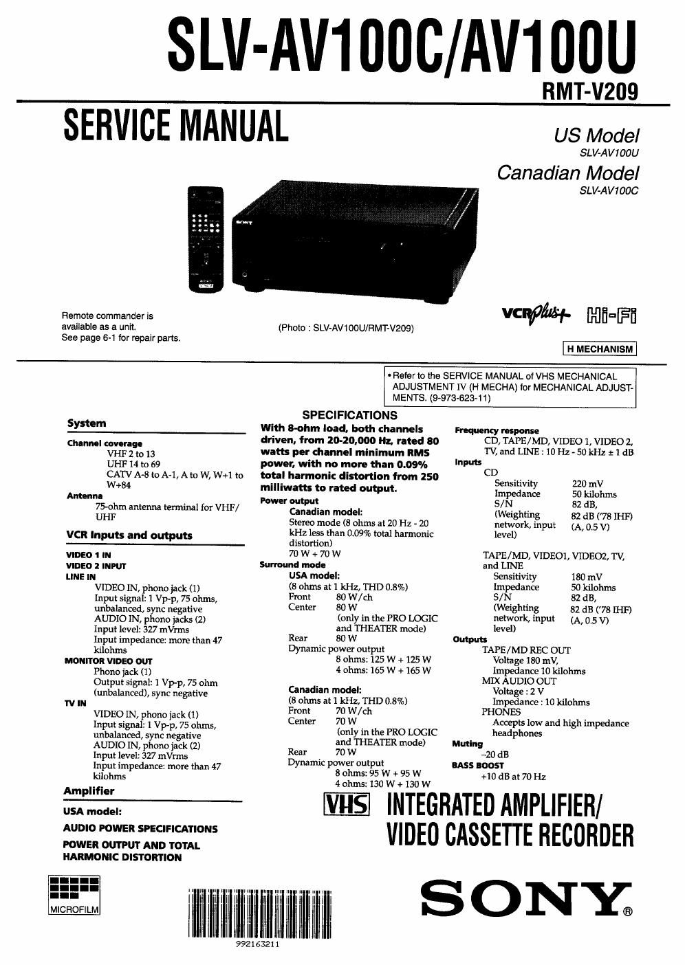
Sony slv av 100 c service manual
This is the 120 pages manual for sony slv av 100 c service manual.
Read or download the pdf for free. If you want to contribute, please upload pdfs to audioservicemanuals.wetransfer.com.
Extracted text from sony slv av 100 c service manual (Ocr-read)
Page 2
:8 dB at 100 Hz and 10 kHz
FM tuner settler!
Tuning range
87.5 - 108.0 MHz
Antenna terminal
75 ohms, unbalanced
AM tuner section
Tuning range
With 10 kHz interval":
530 - 1710 kHz
With 9 kHz interval:
531 . 1710 kHz
Antenna Loop antenna
You can change the AM tuning interval to
General
Power requirement
120 V AC, 60 Hz
Power consumption
190 W
AC outlet
Switched 120 W / 1A MAX
Operating temperature
5°C to 40°C
Storage ten-pent:
-20°C to 60°C
Dlmonslons
Approx. 430 x 157 x 430 mm
(17 x 6'1, x17 inches) (w/h/d)
Supplied nccessorles
Remote commander (1)
Size AA (R6) batteries (2)
75vohm coaxial cable with F-type
connectors (I)
Video cable (1 phono to 1 phone) (ll
AM loop antenna (1)
FM wire antenna (1)
Design and specifications are subject to
change without notice.
9 kHz. After turning in any AM station, includEg projecting parts and
turn off the power, hold down the FM/AM Mm mm"
b tt d th POWER 'tch. T
u on an press e swr 0 USA model:
reset the interval to 10 kHz, repeat the
prodecure.
Approx. 133 kg (29 lb 6 oz)
Canadian model:
Approx. 13.0 kg (28 lb 11 oz)
SAFETY CHECK-OUT
After correcting the original service problem, perform the following
safety checks before releasing the set to the customer:
1. Check the area of your repair for unsoldered or poorly-soldered
connections Check the entire board surface for solder splashes
and bridges
2. Check the interboard wiring to ensure that no wires are pinched"
or contact high-wattage resistors
3. Look for unauthorized replacement parts. particularly transistors,
that were installed during a previous repair. Point them out to
the customer and recommend their replacement.
4. Look for parts which, though functioning, show obvious signs
of deterioration. Point them out to the customer and recommend
their replacement.
5. Check the line cord for cracks and abrasion. Recommend the
replacement of any such line cord to the customer.
6. Check the B+ voltage to see it is at the values specified.
7. Check the antenna terminals, metal trim, metallized knobs,
screws. and all other exposed metal parts for AC leakage. Check
leakage as described below.
To Exposed Metal
Parts on Set
AC
0.15uF > 1.5K! / voltmeter
(0.75V)
'-' Earth Ground
Fig. A. Using an Ac voltmeter to check AC leakage.
LEAKAGE TEST
The AC leakage from any exposed metal part to earth ground and
from all exposed metal parts to any exposed metal part having a
return to chassis, must not exceed 0.5 mA (500 microampers).
Leakage current can be measured by any one of three methods
1. A commercial leakage tester, such as the Simpson 229 or RCA
WT-540A. Follow the manufacturers instructions to use these
instruments.
2. A battery-operated AC milliammcter. The Data Precision 245 digi-
tal multimeter is suitable for this job.
3. Measuring the voltage drop across a resistor by means of aVOM
or battery-operated AC voltmeter. The limit indication is 0.75
V, so analog meters must have an accurate low-voltage scale, The
Simpson 250 and Sanwa SH-63Trd are examples of a passive
VOM that is suitable. Nearly all battery operated digital
multimeters that have a 2V AC range are suitable. (See Fig. A)
SAFETY-RELATED COMPONENT WARNINGI!
COMPONENTS IDENTIFIED BY MARK A OR DO'I'I'ED LINE
WITH MARK A ON THE SOHEMATIC DIAGRAMS AND IN THE
PARTS LIST ARE CRITICAL TO SAFE OPERATION. REPLACE
THESE COMPONENTS WITH SONY PARTS WHOSE PART
NUMBERS APPEAR AS SHOWN IN THIS MANUAL OR IN
SUPPLEMENTS PUBLISHED BY SONY.
ATTENTION AU COMPOSANT AYANT RAPPORT
A LA SECURITE"
LES COMPOSANTS IDENTIFIES PAR UNE MARQUE A SUR LES
DIAGRAMMES SCHEMATIQUES ET LA LISTE DES PIECES SONT
CRITIQUES POUR LA SECURITE DE FONCTIONN.EMENT NE
REMPLACER CES COMPOSANTS QUE PAR DES PIECES SONY
DONT LES NUMEROS SONT DONNES DANS CE MANUEL OU
DANS LES SUPPLEMENTS PUBLIES PAR SONY.
-2-