Sony seq h 3800 service manual

This is the 20 pages manual for sony seq h 3800 service manual.
Read or download the pdf for free. If you want to contribute, please upload pdfs to audioservicemanuals.wetransfer.com.

Page: 1 / 20
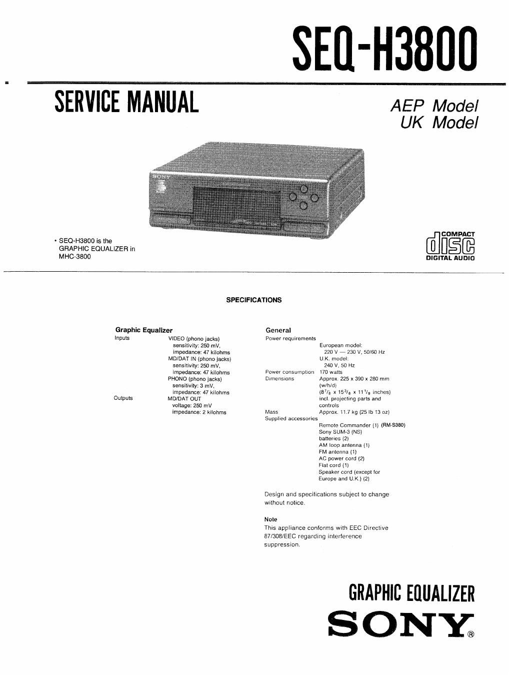
sony seq h 3800 service manual

Extracted text from sony seq h 3800 service manual (Ocr-read)


Page 1

SEII-H380II

SERVICE MANUAL

- SEQ-H3800 is the
GRAPHIC EQUALIZEFI in
MHC-3800

AEP Model
UK Model

COMPACT

DIGITAL AUDIO

SPECIFICATIONS

Graphic Equalizer
Inputs VIDEO (phone jacks)
sensitivity: 250 mV,
impedance: 47 kilohms
MD/DAT IN (phono jacks)
sensitivity: 250 mV,
impedance: 47 kilohms
PHONO (phone iacks)
sensitivity: 3 mV.
impedance: 47 kilohms
Outputs MD/DAT OUT
voltage: 250 mV
impedance: 2 kilahms

General
Power requirements

Power consumption
Dimensmns

Mass
Supplied accessories

European model:

220 V - 230 V. 50/60 HZ
U K, model:

240 V, 50 Hz
70 walls
Approx 225 x 390 x 280 mm
(win/d]
1871;; x 153/a x 11 V5 inches]
Incl projecting parts and
controls
Approx. 11.7 kg (25 It: 13 oz)

Remote Commander (1) (HM-8380)
Sony SUM-3 (NS)

hatterles 12)

AM loop antenna It)

FM antenna (1)

AC power cord (2)

Flat cord (1)

Speaker cord (except tor

Europe and U.K.) (2)

Design and specifications subject to change

without notice.

N ole

This appliance conforms with EEC Directive
87/308/EEC regarding interference

suppression.

GRAPHIC EflUALlZER
S 0 NY;

Page 2

TABLE OF CONTENTS


Section m Fig
SECTION 1. TEST MODE -------------------------------- 3
SECTION 2. GENERAL
Parts Identification ~- ~ - 4
SECTION 3. IC PIN FUNCTION ---------------- --5
SECTION 4. DIAGRAMS
4-]. Block Diagram ........................................ 7
4-2, Printed Wiring Boards
. Main Section ...................................... 11
4-3. Schematic Diagrams
. Main Section ...................................... 15
4-4. Schematic Diagrams
- PaneI,PowerSecti0n ------------------------------- 20
4-5. Printed Wiring Boards
0 Panel, Power Section ------------------------------- 25
4»6. Semiconductor Lead Layouts- 29
4-7. IC Block Diagrams ~- ' 30
SECTION 5. EXPLODED VIEWS
5-1. MAIN Section --------------------------------------- 33
SECTION 6. ELECTRICAL PARTS LIST -------------- 34

SAFETY-RELATED COMPONENT WARNING

COMPONENTS IDENTIFIED BY MARK A OR DOTTED
LINE WITH MARK A ON THE SCHEMATIC DIAGRAMS
AND IN THE PARTS LIST ARE CRITICAL TO SAFE
OPERATION. REPLACE THESE COMPONENTS WITH
SONY PARTS WHOSE PART NUMBERS APPEAR AS
SHOWN IN THIS MANUAL OR IN SUPPLEMENTS PUB-
LISHED BY SONY.