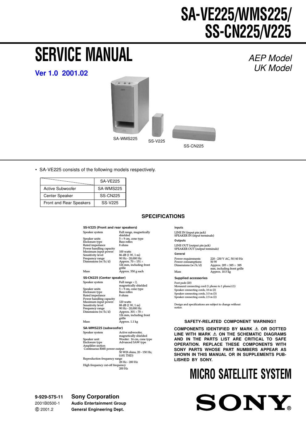
Sony sa ve 225 service manual
This is the 12 pages manual for sony sa ve 225 service manual.
Read or download the pdf for free. If you want to contribute, please upload pdfs to audioservicemanuals.wetransfer.com.
Extracted text from sony sa ve 225 service manual (Ocr-read)
Page 1
2 SA-VE225/WMS225/SS-CN225/V225 SECTION 1 DIAGRAMS 1-1. NOTE FOR PRINTED WIRING BOARDS AND SCHEMATIC DIAGRAMS Note on Printed Wiring Boards: -X: parts extracted from the component side. - : Pattern from the side which enables seeing.Note on Schematic Diagram: -All capacitors are in µF unless otherwise noted. pF: µµF 50 WV or less are not indicated except for electrolytics and tantalums. -All resistors are in Ω and 1/4 W or less unless otherwise specified. -2: nonflammable resistor. -5: fusible resistor. -C: panel designation. -A: B+ Line. -B: B– Line. -Voltages are dc with respect to ground under no-signal conditions. -Voltages are taken with a VOM (Input impedance 10 MΩ). Voltage variations may be noted due to normal produc- tion tolerances. -Signal path. F: AUDIO Note:The components identified by mark 0 or dotted line with mark 0 are critical for safety. Replace only with part number specified.
Page 2
SA-VE225/WMS225/SS-CN225/V225 3 3 THERMAL SHUTDOWN BIPOLAR TRANSCONDACTANCE INPUT STAGE STANDBY/ MUTE BOOST- STRAP MOS GAIN & LEVEL SHIFTING STAGE STBY-GND IN– IN+ IN+ MUTE NC BOOSTSTRAP +VS –VS STBY MUTE NC NC +PWVS OUT –PWVS 1415 12 13 10 11 89 6 7 5 3 4 12 + – MOS OUTPUT STAGESHORT CIRCUIT PROTECTION 1 2 3 4 5 6 7 8 OVER LOAD DET F/F OFFSET DET LATCH/ AUTORESETV CC ON MUTE AC OFF DET OVER LOAD DET OFFSET DET AUTO RESET AC OFF DET GND RELAY DRIVE VCC ON MUTE VCC - IC Block Diagrams – MAIN Board – IC302µPC1237HA -Circuit Boards Location SA-WMS225 POWER IC board POWER SW board LED board CONTROL boardMAIN board – POWER IC Board – IC401 TDA7294