Sony sava 57 service manual

This is the 8 pages manual for sony sava 57 service manual.
Read or download the pdf for free. If you want to contribute, please upload pdfs to audioservicemanuals.wetransfer.com.

Page: 1 / 8
sony sava 57 service manual

Extracted text from sony sava 57 service manual (Ocr-read)


Page 1

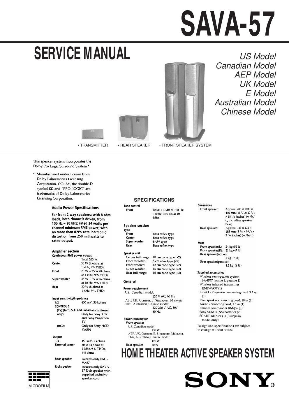
SAVA-57

SERVICE MANUAL

- TRANSMITTER

- REAR SPEAKER

US Model
Canadian Model
AEP Model

UK Model

E Model
Australian Model
Chinese Model

- FRONT SPEAKER SYSTEM

This speaker system incorporates the
Dolby Pro Logic Surround System.

' Manufactured under license from
Dolby Laboratories Licensing
Corporation DOLBY, the double-D
symbol III and "PRO LOGIC are
trademarks of Dolby Laboratories
Licensing Corporation.

Audio Power Specifications

For front 2 way speakers: with 8 ohm
loads. both channels driven. from
100 Hz - 20 kHz; rated 24 watts per
(hannel minimum llMS power, with
no more than 0.9% total harmonic
distortion from 250 milliwatts to
rated output.

Amplifier section
Continuous RMS power output

MICROFILM

Total 200 W
Center 50 W (I ohms at
1 kHz, 9% THD)
from 75 W t 25 W 18 ohms
at 1 kHz, 9 % THDl
Super wooler 35 W + 35 W (6 ohms
at .10 Hz, 9 2%. THD)
Rear 30 w (3 ohm at
1 kHz, 9 0/. THD)
Input tensilivilyllmpedanre
ill 45') mV, 50 kohms
CONTROL S
(W) (for U.SA. and Cal-amen otstomer:
only) Only for Sony XBR
and Sony Projection
TV
(RCD) Only tor Sony HCD-
VASSD
Output
ill 450 mV, 1 kohms
External center 50 W (4 ohms at
1 kHz, 9 7. film,
L8 ohms
Rear spedler Accepts only EMT -
VA57
l'Hh speaker Accepts only SAVA-
57 R-ch speaker with
supplied exclusive
speaker cord

SPECIFICATIONS
Tone control
Front Bass: :10 dB at loo Hz
Treble: :10 dB at it:
kHz

Speaker section

Type
Front Bass reflex type
Center Bass reflex type
Super mater SAW type
Rear Bass reflex type
Speaker unit
Canter tutl range: 10 cm can type (x2)
From rweeten 5 cm cone type (x1)
Front woofer: 12 em cone type 1x2)
Super woaten l6 cm cone type 00.)
Rear tull range: lo Cm cone type (x2)
General
Power requirement
US. Canadian modal:
110 V AC, 60 Hz

AER UK, German, E, Singapore, Malaysia,
Thai, Auslraliali, Chinese liiudel

220-230 V AC, 50/

60 Hz

Power consumpllon
Front speaker
US Canadian model
130 W
AER UK German, E Singapore. Malaysia.
Tllal, AusLllIlZln Chinese model
120 W
Rear speaker 30 w

Dimensions
Front speakzt: Approx. 235 x 1100 x
460 mm [11 Vtxfl /t
x15/a inches) iw/h/
a. including speaker
base)
Rear speaker. Approx 135 x 735 x
135 ram (5 Viral/ix
7 Vi inches} (W/h/d)
Mass

Front speakerlL): :4 kg (53 lb)
Front speaketnz): 2i kg (47 lb)
Rear speakeriartive):

3 kg (71b)
Rearspeakefipassive):

15 kg (4 lb)

Supplied accessories
Wireless rear speaker system
SA-IF57 (active l, passive 1)
Wireless infrared transmitter
EMT-VA57(1)
Front L/R speaker connecting Card, 3.5 m
(1]
Rear speaker connecting cord, 10 m (1)
Audio connecting curd, 1.5 m (1)
Remote commander RM-JS7 (1)
Sony SUM-3 (NS) batteries (2)
SCART adaptor (1) (European
model only)

Design and spectficallons are subject
lo change without nolice.

HOM E THEATER ACTIVE SPEAKER SYSTEM

ONY;

Page 2

SECTION 4
TEST MODE

MODE ALL FLUORESCENT INDICATOR TUBES LIGHT

When the AC plug is inserted to the power outlet with pressing the

MASTER VOL + button, the all fluorescent indicator tubes light.
KEY CHECK, LED LIGHTING MODE

1. Pull out the AC plug from the power outlet and turn the power
OFF.

2. Connect the lead wire to TP3 on the KEY board.

3. Insert the AC plug to the power outlet and set to STANDBY
mode.

4. Let the lead wire connected in step 1 Contact to the ground.

5. All fluorescent indicator tubes light, and enter the key check
mode.

6 Pressing any buttons, the number of button will be displayed on
the fluorescent indicator tube.

7. After all buttons are pressed, it will be in the STANDBY mode.

Button Button Number LED Color
POWER 2 Red
MASTER VOL 7 3 Green
MASTER VOL + 4 Red
INPUT 5 Green
SURROUND 6 Red
CTR MODE 7 Green
S.WOOFER 8 Red

Note:
1. The LED (D505) lights while pressing each button.
The LED lights in red when even number of buttons are pressed,
and it lights in green when odd number of buttons are pressed.
2. The LED lights even when the pressed button is pressed again.

Parts Location

[KEY BOARD] - Conductor side -

SECTION 5
ELECTRICAL ADJUSTMENT

CARRIER FREQUENCY Adjustment
Note:

Set the transmitter to the users environment, connect it to the front
speaker, and supply the power. (Refer to Service Note.)

Setting:
TP5
frequency counter
:| Transmitter
+ board
7 | R226
# i\
TP6

Procedure:

1. Connect the frequency counter to TPS and TP6 of the two ends
of the resistor (R226) of the TRANSMITTER board.

2. Turn ON the power of the front speaker.

3. Adjust L201 of the TRANSMITTER board, and adjust so that
the reading of the frequency counter is 4.3 MHZ i 0.01 MHZ.

RECEIVING FREQUENCY, MUTING LEVEL adjustment

Note:

Perform procedure 1 if using FM RF SSG and procedure 2 if not.
However, as procedure 2 is a simple procedure, adjustment is not
accurate.

- Procedure 1

Setting:
level meter
FM RF SSG TP7
® Receiver C 3 Emil/er
board C | 3 oar
L 1 # TP1 02

Carrier frequency : 4.3MHz TPB

Modulation .' no modulation
Output level .' 40118 (at 75 9. open)

Procedure:

1. Connect SSG to TP7 and TP8 of the two ends ofthe coil (Ll) of
the RECEIVER board.

2. Set the output level of SSG to 40 dB.

3. Insert the AC plug of the unit to the power outlet and supply the
power.

4. Adjust IFT103 of the RECEIVER board, and adjust so that the
voltage of both ends ofTP102 becomes 0V. (RECEIVING FREA
QUENCY adjustment)

5. Adjust the output level of SSG to 22 dB.

6. Adjust RV102 until D109 turns green from red. (MUTING
LEVEL adjustment)