Sony rm nx 7000 service manual

This is the 28 pages manual for sony rm nx 7000 service manual.
Read or download the pdf for free. If you want to contribute, please upload pdfs to audioservicemanuals.wetransfer.com.

Page: 1 / 28
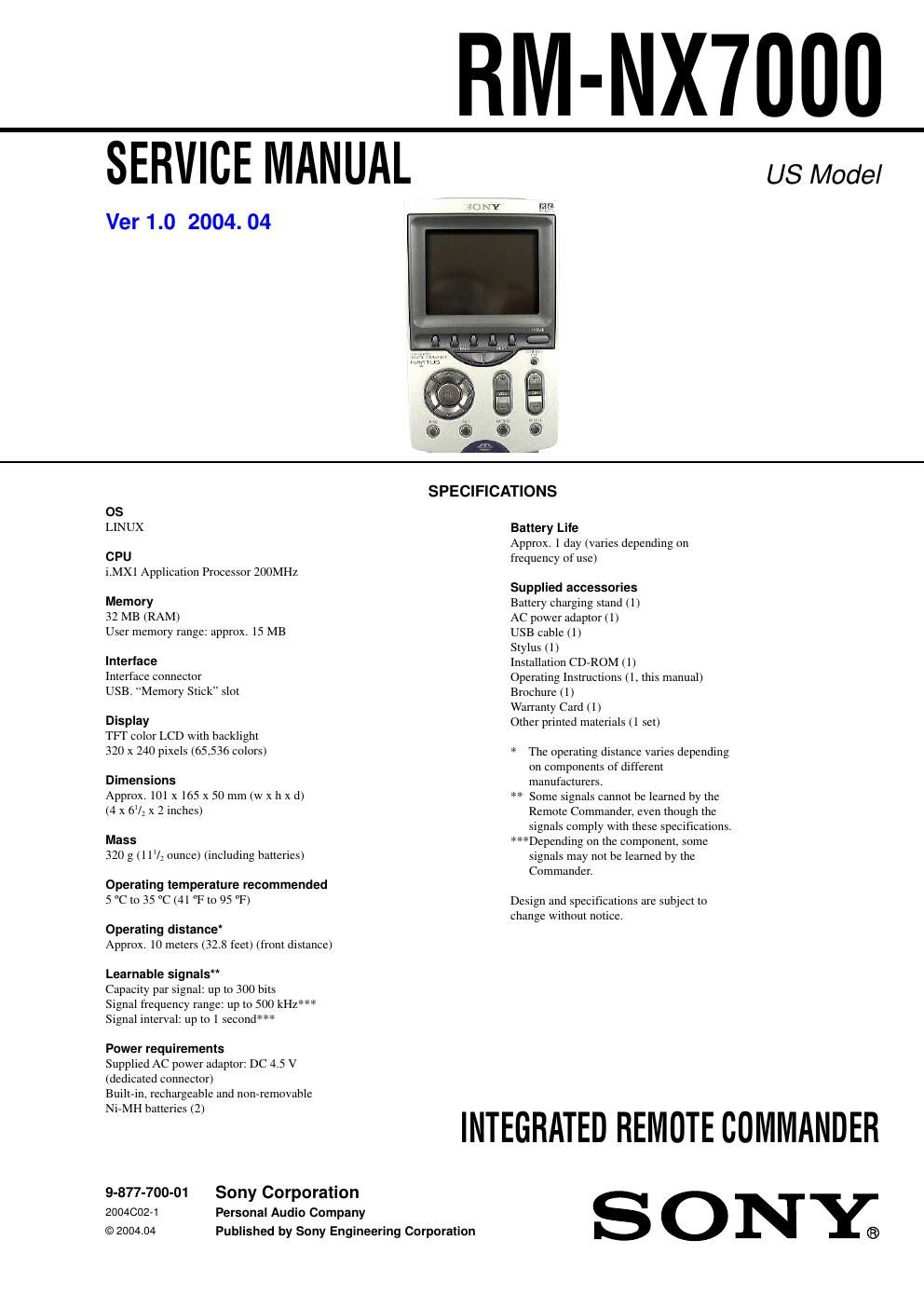
sony rm nx 7000 service manual

Extracted text from sony rm nx 7000 service manual (Ocr-read)


Page 1

RM-NX7000

SERVICE MANUAL

Ver 1.0 2004. 04

US Model

OS
LINUX

CPU
i.MX1 Application Processor 200MHz

Memory
32 MB (RAM)
User memory range: approx. 15 MB

Interface
Interface connector
USB. Memory Stick slot

Display
TFI' color LCD with backlight
320 x 240 pixels (65,536 colors)

Dimensions
Approx. 101 x 165 x 50 mm (w x h x d)
(4 x 6V3 x 2 inches)

MESS
320 g(11/2 ounce) (including batteries)

Operating temperature recommended
5 C to 35 C (41 F to 95 °F)

Operating distance
Approx. 10 meters (32.8 feet) (front distance)

Learnable signals"

Capacity par signal: up to 300 bits

Signal frequency range: up to 500 kHz***
Signal interval: up to 1 second***

Power requirements

Supplied AC power adaptor: DC 4.5 V
(dedicated connector)

Built-in, rechargeable and non-removable
Ni-MH batteries (2)

SPECIFICATIONS

Battery Life
Approx. 1 day (varies depending on
frequency of use)

Supplied accessories

Battery charging stand (1)

AC power adaptor (1)

USB cable (1)

Stylus (1)

Installation CD-ROM (1)

Operating Instructions (1, this manual)
Brochure (1)

Warranty Card ( 1)

Other printed materials (1 set)

* The operating distance varies depending
on components of different
manufacturers.

** Some signals cannot be learned by the
Remote Commander, even though the
signals comply with these specifications.

***Depending on the component, some
signals may not be learned by the
Commander.

Design and specifications are subject to
change without notice.

INTEGRATED REMOTE COMMANDER

9-877-700-01 Sony Corporation
200400271 Personal Audio Company N Y
(o 2004.04 Published by Sony Engineering Corporation ®

Page 2

RM-NX7000

TABLE OF CONTENTS

Specifications ............................................................................ 1

1. GENERAL ................................................................... 3

2. DISASSEMBLY

2-1. Disassembly Frow ........................
2-2. Case (Lower) Nickel Hydrogen Battery .
2-3. Case (Upper) Block Assy .............
2-4. Switch Block A 'sy
2-5. Main Board


3. TEST MODE ............................................................... 8

4. DIAGRAM

4-1. Block Diagram 7 Main Section (1/2)
4-2. Block Diagram 7 Main Section (2/2)
4-3. Shematic Diagram 7 Main Section (1/6) 7
4-4. Shematic Diagram 7 Main Section (2/6) 7
4-5. Shematic Diagram 7 Main Section (3/6) 7
4-6. Shematic Diagram 7 Main Section (4/6) 7
4-7. Shematic Diagram 7 Main Section (5/6) 7
4-8. Shematic Diagram 7 Main Section (6/6) 7 ......
4-9. Plinted Wiring Board 7 Main Section (Side A) 7
4- 10. Plinted Wiring Board 7 Main Section (Side B) 7
4-11. Shematic Diagram 7 LED Section 7 .
4-12. Plinted Wiring Board 7 LED Section 7


5. EXPLODED VIEWS ................................................. 21

6. ELECTRICAL PARTS LIST .................................. 22

Flexible Circuit Board Repairing
- Keep the temperature of the soldering iron around 270°C
during repairing.
- Do not touch the soldering iron on the same conductor of the
circuit board (within 3 times).
- Be careful not to apply force on the conductor when soldering
or unsoldering.

Notes on chip component replacement
- Never reuse a disconnected chip component.
- Notice that the minus side of a tantalum capacitor may be
damaged by heat.

- Memory Stick and are trademarks of Sony Corporation.

- Memory Stick Duo, MEMURV Snrxfluu and Memory Stick PRO"
are trademarks of Sony Corporation.

~TouchEngine is a trademark of Sony Corporation.

- Microsoft and Windows are registered trademarks of Microsoft
Corporation in the United States and/or other countries.

- All other names of systems and products are trademarks or
registered trademarks of their respective owners. TM and 9 marks
are omitted in this manual.

- Microsoft® Windows® XP Professional and Microsoft® Windows®
XP Home Edition are mentioned as Windows XP in this manual.

- Microsoft® Windows® 2000 Professional is mentioned as Windows
2000 in this manual.

- Microsoft® Windows® Millennium Edition is mentioned as
Windows Me in this manual.

- Microsoft® Windows® 98 Second Edition is mentioned as Windows
98 SE in this manual.

Unleaded solder

Boards requiring use of unleaded solder are printed with the lead-
free mark (LF) indicating the solder contains no lead.

(Caution: Some printed circuit boards may not come printed with
the lead free mark due to their particular size.)

I" : LEAD FREE MARK
Unleaded solder has the following characteristics.

Unleaded solder melts at a temperature about 40°C higher than
ordinary solder.
Ordinary soldering irons can be used but the iron tip has to be
applied to the solderjoint for a slightly longer time
Soldering irons using a temperature regulator should be set to
about 350°C.
Caution: The printed pattern (copper foil) may peel away if
the heated tip is applied for too long, so be careful!

Strong viscosity
Unleaded solder is more viscous (sticky, less prone to flow)
than ordinary solder so use caution not to let solder bridges
occur such as on IC pins, etc.

Usable with ordinary solder
It is best to use only unleaded solder but unleaded solder may
also be added to ordinary solder.

Note on chip component replacement
Never reuse a disconnected chip component.
Notice that the minus side of a tantalum capacitor may be
damaged by heat.

ICl (microcomputer) and IC7 (flash RAM) on Main board
cannot be replaced individually.
Replace it with Main board assembly for service.