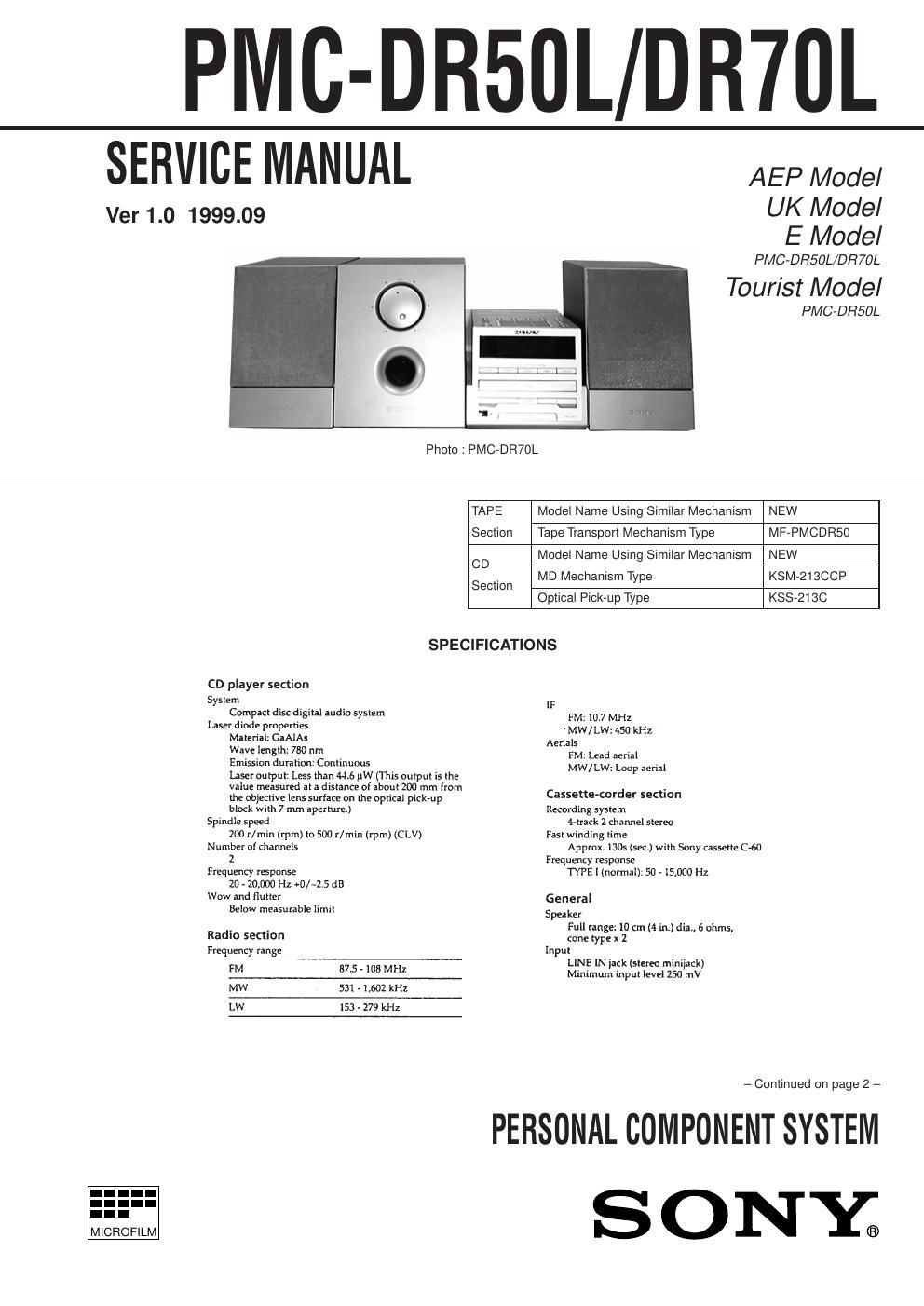
Sony pmc dr 50 pmc dr 70l
This is the 9 pages manual for sony pmc dr 50 pmc dr 70l.
Read or download the pdf for free. If you want to contribute, please upload pdfs to audioservicemanuals.wetransfer.com.
Extracted text from sony pmc dr 50 pmc dr 70l (Ocr-read)
Page 1
Ð 39 ÐÐ 41 Ð Ð 40 Ð 5-5. SCHEMATIC DIAGRAM Ð MAIN SECTION (1/3) Ð PMC-DR50L/DR70L Note: ¥ All capacitors are in mF unless otherwise noted. pF: mmF 50 WV or less are not indicated except for electrolytics and tantalums. ¥ All resistors are in W and 1/4 W or less unless otherwise specified. ¥ ¢ : internal component. ¥U: B+ Line. ¥H: adjustment for repair. ¥ Voltages and waveforms are dc with respect to ground under no-signal (detuned) conditions. no mark : FM ( ) : MW <>: LW ¥ Voltages are taken with a VOM (Input impedance 10 MW). Voltage variations may be noted due to normal produc- tion tolerances. ¥ Waveforms are taken with a oscilloscope. Voltage variations may be noted due to normal produc- tion tolerances. ¥ Circled numbers refer to waveforms. ¥ Signal path. F: FM f: MW L: LW r Waveforms Ð MAIN SECTION (1/3) Ð r Refer to page 74 for IC Block Diagram. 1 IC3 @Á 2 VOLT/DIV : 0.5 V AC TIME/DIV : 5 msec IC4 !¢ VOLT/DIV : 0.2 V AC TIME/DIV : 50 nsec 1.5Vp- p 75kHz 556mVp- p 4.332MHz
Page 2
Ð 42 ÐÐ 44 Ð Ð 43 Ð PMC-DR50L/DR70L 5-6. SCHEMATIC DIAGRAM Ð MAIN SECTION (2/3) Ð r Refer to page 74 for IC Block Diagrams. r Refer to page 45 for Waveforms. r Refer to page 45 for Notes.