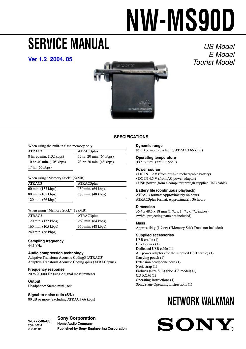
Sony nw ms 90 d service manual

This is the 26 pages manual for sony nw ms 90 d service manual.
Read or download the pdf for free. If you want to contribute, please upload pdfs to audioservicemanuals.wetransfer.com.

Page: 1 / 26
sony nw ms 90 d service manual

Extracted text from sony nw ms 90 d service manual (Ocr-read)


Page 1

2 NW-MS90D Unleaded solder Boards requiring use of unleaded solder are printed with the lead- free mark (LF) indicating the solder contains no lead. (Caution: Some printed circuit boards may not come printed with the lead free mark due to their particular size.) : LEAD FREE MARK Unleaded solder has the following characteristics. -Unleaded solder melts at a temperature about 40 °C higher than ordinary solder. Ordinary soldering irons can be used but the iron tip has to be applied to the solder joint for a slightly longer time. Soldering irons using a temperature regulator should be set to about 350 °C. Caution: The printed pattern (copper foil) may peel away if the heated tip is applied for too long, so be careful! - Strong viscosity Unleaded solder is more viscous (sticky, less prone to flow) than ordinary solder so use caution not to let solder bridges occur such as on IC pins, etc. - Usable with ordinary solder It is best to use only unleaded solder but unleaded solder may also be added to ordinary solder. z USABLE FORMAT Use ISO9660 Level 1 format. - IC401 (microcomputer), IC451 (frash RAM) on Main board cannot be replaced individually. Replace it with Main board assembly for service. - IC461, 463 (frash RAM) on NAND board cannot be replaced individually. Replace it with NAND board assembly for service. - When exchanging NAND board sub ASSY (for service), SL701 of the B-side may be open. In this case, please perform the solder bridge of SL701. T ABLE OF CONTENTS Specifications ........................................................................\ .... 1 1. SERVICING NOTES ................................................ 3 2. GENERAL ................................................................... 3 3. TEST MODE ............................................................... 4 4. DISASSEMBLY 4-1. Case (U) Sub Assy, Play Unit .......................................... 5 4-2. Lcd Board ........................................................................\ 5 4-3. Button (MS) Assy, Chassis (R) Assy ............................... 6 4-4. NI-MH Battery, Power Board ......................................... 6 4-5. Nand Board, Main Board ................................................ 7 5. DIAGRAMS 5-1. Block Diagrams ............................................................... 9 5-2. Schematic Diagram – Main Section (1/2)– ..................... 10 5-3. Schematic Diagram – Main Section (2/2)– ..................... 11 5-4. Printed Wiring Boards – Main Section– .......................... 12 5-5. Schematic Diagram – Lcd Section– ................................ 13 5-6. Printed Wiring Boards – Lcd Section– ............................ 14 5-7. Schematic Diagram – Nand Section– .............................. 15 5-8. Printed Wiring Boards– Nand Section– .......................... 16 5-9. Schematic Diagram – Power Section– ............................ 17 5-10. Printed Wiring Boards– Power Section– ......................... 18 6. EXPLODED VIEWS 6-1. Case Section .................................................................... 20 6-2. Chassis Section ................................................................ 21 7. ELECTRICAL PARTS LIST .................................. 22 Flexible Circuit Board Repairing -Keep the temperature of the soldering iron around 270 °C during repairing. - Do not touch the soldering iron on the same conductor of the circuit board (within 3 times). - Be careful not to apply force on the conductor when soldering or unsoldering. Notes on chip component replacement -Never reuse a disconnected chip component. - Notice that the minus side of a tantalum capacitor may be damaged by heat. OpenMG and its logo are trademarks of Sony Corporation. SonicStage and its logo are trademarks of Sony Corporation. MagicGate Memory Stick is trademark of Sony Corporation. Memory Stick and are trademarks of Sony Corporation. Memory Stick Duo and are trademarks of Sony Corporation. MagicGate and are trademarks of Sony Corporation. A TRAC, ATRAC3, ATRAC3plus and their logos are trademarks of Sony Corporation. Microsoft, Windows and Windows Media are trademarks or registered trademarks of Microsoft Corporation in the United States and/or other countries. US and foreign patents licensed from Dolby Laboratories. All other trademarks and registered trademarks are trademarks or registered trademarks of their respective holders. In this manual, TM and R marks are not specified. V er 1.2

Page 2

3 NW-MS90D SECTION 2 GENERAL This section is extracted from instruction manual. Locating controls For details about each part, refer to the pages in parentheses. Network Walkman Rear side Front side 1 VOL (+/–) control 2 Headphone plug 3 Plug cover 4 SOUND/AVLS button 5 Memory Stick Eject button 6 Display 7 Shuttle switch 8 Play/Stop button 9 RESET button 0 USB cradle connector qa HOLD (Locking controls) switch qs MENU button You can switch to the Time display by pressing the MENU button for a while. qd Access lamp qf Memory Stick slot SECTION 1 SERVICING NOTES [ Notes on using Memory Stick Duo ] - Do not remove Memory Stick Duo during reading or writing data. - Data may be damaged in the following cases. – The Network Walkman is removed from the USB cradle or the dedicated USB cable is unpl\ ugged while reading or writing data. – The Memory Stick is used in a location subject to static electri\ city or electric noise. - Creating backup copies of important data is recommended. [ Notes on formatting (initializing) ] Memory Stick Duo is shipped with a FAT format as the standard format. To format Memory Stick, please use devices conformable with the \ Memory Stick. If Memory Stick is formatted using Windows Explorer, FORMAT ERROR will be displayed and audio files cannot be played on the Network Walkman. On Windows XP, you can format Memory Stick properly. When you format Memory Stick, always perform either one of the following: - Follow the instructions of Formatting memory. - Format using the supplied Sonic Stage software. For details on how to format using the Sonic Stage software, refer to \ Sonic Stage Online Help: Initializing an MG Memory Stick . [ Displaying on Windows Explorer ] When you connect Network Walkman to your computer with the supplied USB cable, you can display the\ data stored on Memory Stick or built-in flash memory as an external drive (for example, a\ s the D drive) using Windows Explorer. -Data transferred with the Sonic Stage software will be stored in a H\ IFI folder. Do not edit data stored in the HIFI folder using W indows Explorer. Data copied or edited using Windows Explorer cannot be played on your Network Walkman. -Y ou can display data that has been stored on other Memory Stick c\ ompatible devices (JPEG,MPEG format, etc.,). For information on how to handle data except in the HIFI folder, refer to the instruction manual that comes with the equipmen t with which the recording has been done.