Sony mz rh 1 service manual

This is the 66 pages manual for sony mz rh 1 service manual.
Read or download the pdf for free. If you want to contribute, please upload pdfs to audioservicemanuals.wetransfer.com.

Page: 1 / 66
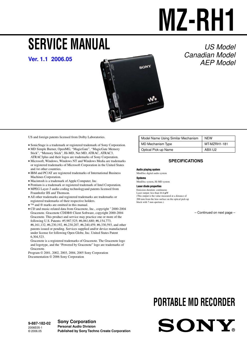
sony mz rh 1 service manual

Extracted text from sony mz rh 1 service manual (Ocr-read)


Page 1

MZ-RH1 2 Recording and playback timeList of the recording time for each disc (Approx.)The recording time is varied depending on disc type, disc mode, codec, and bit rate. When using a disc in Hi-MD mode When recording on the recorder Recording time 1) Codec/ Bit rateRecording mode on the recorder1GB Hi-MD disc80-minute standard disc 74-minute standard disc60-minute standard disc LinearPCM/ 1.4 Mbps PCM 1 hour and 34 minutes28 minutes 26 minutes 21 minutes A TRAC ATRAC3plus / 256 kbps Hi-SP 7 hours and 55 minutes2 hours and 20 minutes 2 hours and 10 minutes1 hour and 40 minutes A TRAC3plus / 64 kbps Hi-LP 34 hours 10 hours and 10 minutes9 hours and 20 minutes7 hours and 40 minutes When transferring from the computer Recording time 1) Codec/Bit rate 1GB Hi-MD disc80-minute standard disc 74-minute standard disc60-minute standard disc LinearPCM/1.4 Mbps 1 hour and 34 minutes28 minutes 26 minutes 21 minutes A TRAC ATRAC3plus /352 kbps 5 hours and 30 minutes1 hour and 35 minutes 1 hour and 30 minutes1 hour and 10 minutes A TRAC3plus /256 kbps 7 hours and 55 minutes2 hours and 20 minutes 2 hours and 10 minutes1 hour and 40 minutes A TRAC3plus /192 kbps 11 hours 3 hours and 10 minutes3 hours 2 hours and 20 minutes A TRAC3plus /64 kbps 34 hours 10 hours and 10 minutes9 hours and 20 minutes7 hours and 40 minutes A TRAC3plus /48 kbps 45 hours 13 hours and 30 minutes12 hours and 30 minutes10 hours A TRAC3 /132 kbps 16 hours and 30 minutes4 hours and 50 minutes 4 hours and 30 minutes3 hours and 40 minutes A TRAC3 /105 kbps 20 hours and 40 minutes6 hours and 10 minutes 5 hours and 40 minutes4 hours and 40 minutes A TRAC3 /66 kbps 32 hours and 40 minutes9 hours and 50 minutes 9 hours 7 hours and 20 minutes MP3 2)/128 kbps 17 hours 5 hours 4 hours and 30 minutes3 hours and 30 minutes 1) When transferring 4-minute tracks 2) MP3 file formats are as follows: MPEG-1 Audio Layer-3/sampling fre\ quency 44.1 kHz/fixed bit rate. RevolutionsApprox. 350 rpm to 3,600 rpm (CLV) Error correctionHi-MD: LDC (Long Distance Code)/BIS (Burst Indicator Subcode) MD: ACIRC (Advanced Cross Interleave Reed Solomon Code) Sampling frequency44.1 kHz Sampling rate converterOptical (digital) input: 32 kHz/44.1 kHz/48 kHz Audio formats supported by this recorderRecording: LinearPCM (44.1 kHz/16 bit) A TRAC3plus (Hi-SP, Hi-LP) A TRAC3 (LP2, LP4) A TRAC (SP) Playback: LinearPCM A TRAC3plus A TRAC3 A TRAC MP3 (for playback only) (MPEG-1 Audio Layer-3, sampling frequency 32/44.1/48 kHz, bit rate 32-320 kbps (fixed/variable bit rate)) A TRAC stands for Adaptive TRansform Acoustic Coding . Modulation systemHi-MD: 1-7RLL (Run Length Limited)/PRML (Partial Response Maximum Lik\ elihood) MD: EFM (Eight to Fourteen Modulation) Frequency response (During digital and analog input)20 to 20,000 Hz ±3 dB Input connectors*MIC (PLUG IN POWER): stereo mini-jack (minimum input level 0.13 mV) LINE IN (OPT): stereo mini-jack for analog input (minimum input level\ 49 mV)/optical (digital) mini-jack for optical (digital) input Output connectori/LINE OUT: stereo mini-jack (dedicated remote jack) / regulated output\ 194 mV (10 k Ω) Maximum output (DC)Headphones: 4.5 mW + 4.5 mW (16 Ω) (European model) 5 mW + 5 mW (16 Ω) (Other models) Power requirementsSony AC Power Adaptor DC 5 V AC 100 V - 240 V, 50/60 HzLithium-ion rechargeable battery LIP-4WM, 3.7 V, 370 mAh, Li-ion Operating temperature+5 °C (+41 °F) to +35 °C (+95 °F) Battery operation time** Dimensions Approx. 83.8 × 84.4 × 14.7 mm (w/h/d) (33/8 3/8 19/32 in.) (excluding projecting parts and controls) MassApprox. 96 g (3.4 oz.) (the recorder only) Approx. 106 g (3.8 oz.) (including the rechargeable battery) * The LINE IN (OPT) jack is used to connect either a digital (optical)\ cable or a line (analog) cable. ** Measured in accordance with JEITA. Design and specifications are subject to change without notice. Battery life 1) This value varies depending on how the recorder is used. When recording/playing continuously in Hi-MD mode (Unit: approx. hours) When Disc type LinearPCM Hi-SP Hi-LP MP3 2) Recording 1GB Hi-MD disc 6 9 10.5 - 3) 60/74/80-minute standard disc 59 10.5 - 3) Playing 1GB Hi-MD disc 10 15.5 19 16.5 60/74/80-minute standard disc 8 14.5 18.5 16 When recording/playing continuously in MD mode (Unit: approx. hours) When Disc type SP LP2 LP4Recording 60/74/80-minute standard disc 8.5 10.5 12 Playing 60/74/80-minute standard disc 15.5 17.5 19 Measured in accordance with the JEITA (Japan Electronics and Information Technology Industries Association) standard. 1) Measured using a fully charged lithium-ion rechargeable battery with EL Light in the menu set to Auto Off 2) When transferring at 128 kbps3) The recorder cannot record in MP3 mode. Transfer MP3 audio data using the supplied SonicStage software NoteRepeated recharging causes the capacity of the rechargeable battery to decrease over time. As a result, the battery life will become shorter as the battery is used. Please replace the batt\ ery when the battery life reaches about half the time listed above. × 3 × Supplied accessories- AC power adaptor (100 V - 240 V) - AC power cord 1) - USB cable - Remote control 2) - Earphones - LIP-4WM Lithium-ion rechargeable battery - Rechargeable battery case - Optical cable (for the European model) - Carrying pouch - Ferrite core (small size) − Three for the European model − Two for the North American model - 1GB Hi-MD disc (except for the European model) - CD-ROM 3) (Windows: SonicStage/MD Simple Burner, Macintosh: Hi-MD Music Transfer \ for Mac) - Operating Instructions (this manual) - Operating Instructions (Hi-MD Music Transfer for Mac) 1) The shape of the plug differs according to the region where the recorder\ was purchased. Two cords with differently shaped plugs are supplied with the models for\ Europe, Asia and Chile. Use the one that corresponds with the outlet configuration in the regi\ on where it is used. 2) For the North American and Latin American models, remote with a ferrite \ core is supplied.3) Do not play a CD-ROM on an audio CD player. For details on Hi-MD Music Transfer for Mac, refer to the instru\ ction sheet supplied with this recorder.

Page 2

MZ-RH1 3 TABLE OF CONTENTS 1. SERVICING NOTES ............................................... 4 2. GENERAL ................................................................... 5 3. DISASSEMBLY 3-1. Disassembly Flow ........................................................... 6 3-2. Panel (Lower) Section ..................................................... 6 3-3. Cabinet (Front) Section ................................................... 7 3-4. MAIN Board .................................................................... 7 3-5. Panel (Upper) Assy .......................................................... 8 3-6. Mechanism Deck (MT-MZRH1-181) ............................. 8 3-7. Torsion Spring (Pop Up L), Torsion Spring (Pop Up R) .............................................. 9 3-8. Gear (SA), Gear (SB) ...................................................... 9 3-9. OP Service Assy (ABX-U2) ............................................ 10 3-10. DC Motor SSM18D/C-NP (Spindle) (M701), DC Motor (Sled) (M702), DC Motor Unit (Over Write Head Up/Down) (M703) ... 10 3-11. Holder Assy ..................................................................... 11 3-12. Position of Ferrite Core ................................................... 11 4. TEST MODE .............................................................. 12 5. ELECTRICAL ADJUSTMENTS ......................... 16 6. DIAGRAMS 6-1. Block Diagram – SERVO Section – ................................ 21 6-2. Block Diagram – AUDIO Section – ................................ 22 6-3. Block Diagram – POWER SUPPLY Section – ............... 23 6-4. Schematic Diagram – MAIN Section (1/7) – .................. 25 6-5. Schematic Diagram – MAIN Section (2/7) – .................. 26 6-6. Schematic Diagram – MAIN Section (3/7) – .................. 27 6-7. Schematic Diagram – MAIN Section (4/7) – .................. 28 6-8. Schematic Diagram – MAIN Section (5/7) – .................. 29 6-9. Schematic Diagram – MAIN Section (6/7) – .................. 30 6-10. Schematic Diagram – MAIN Section (7/7) – .................. 31 6-11. Printed Wiring Board – MAIN Board (Component Side) – ............................... 32 6-12. Printed Wiring Board – MAIN Board (Conductor Side) – ................................. 33 6-13. Printed Wiring Board – OLED Board – .......................... 34 6-14. Schematic Diagram – OLED Board – ............................. 35 7. EXPLODED VIEWS 7-1. Panel (Upper) Section ..................................................... 52 7-2. Cabinet (Front) Section ................................................... 53 7-3. Lower Panel Section ........................................................ 54 7-4. Set Chassis Section .......................................................... 55 7-5. MAIN Board Section ....................................................... 56 7-6. Mechanism Deck Section (MT-MZRH1-181) ................ 57 8. ELECTRICAL PARTS LIST ................................ 58 Notes on chip component replacement - Never reuse a disconnected chip component. - Notice that the minus side of a tantalum capacitor may be damaged by heat. Flexible Circuit Board Repairing - Keep the temperature of the soldering iron around 270 ˚C during repairing. - Do not touch the soldering iron on the same conductor of the circuit board (within 3 times). - Be careful not to apply force on the conductor when soldering or unsoldering. CAUTION Use of controls or adjustments or performance of procedures other than those specified herein may result in hazardous radiation e xposure. SAFETY-RELATED COMPONENT WARNING!! COMPONENTS IDENTIFIED BY MARK 0 OR DOTTED LINE WITH MARK 0 ON THE SCHEMATIC DIAGRAMS AND IN THE PARTS LIST ARE CRITICAL TO SAFE OPERATION. REPLACE THESE COMPONENTS WITH SONY PARTS WHOSE PA RT NUMBERS APPEAR AS SHOWN IN THIS MANUAL OR IN SUPPLEMENTS PUBLISHED BY SONY. ATTENTION AU COMPOSANT AYANT RAPPORT À LA SÉCURITÉ! LES COMPOSANTS IDENTIFIÉS PAR UNE MARQUE 0 SUR LES DIAGRAMMES SCHÉMATIQUES ET LA LISTE DES PIÈCES SONT CRITIQUES POUR LA SÉCURITÉ DE FONCTIONNEMENT. NE REMPLACER CES COM- POSANTS Q UE PAR DES PIÈCES SONY DONT LES NUMÉROS SONT DONNÉS DANS CE MANUEL OU DANS LES SUPPLÉMENTS PUBLIÉS PAR SONY.