Sony mz r 909 service manual

This is the 86 pages manual for sony mz r 909 service manual.
Read or download the pdf for free. If you want to contribute, please upload pdfs to audioservicemanuals.wetransfer.com.

Page: 1 / 86
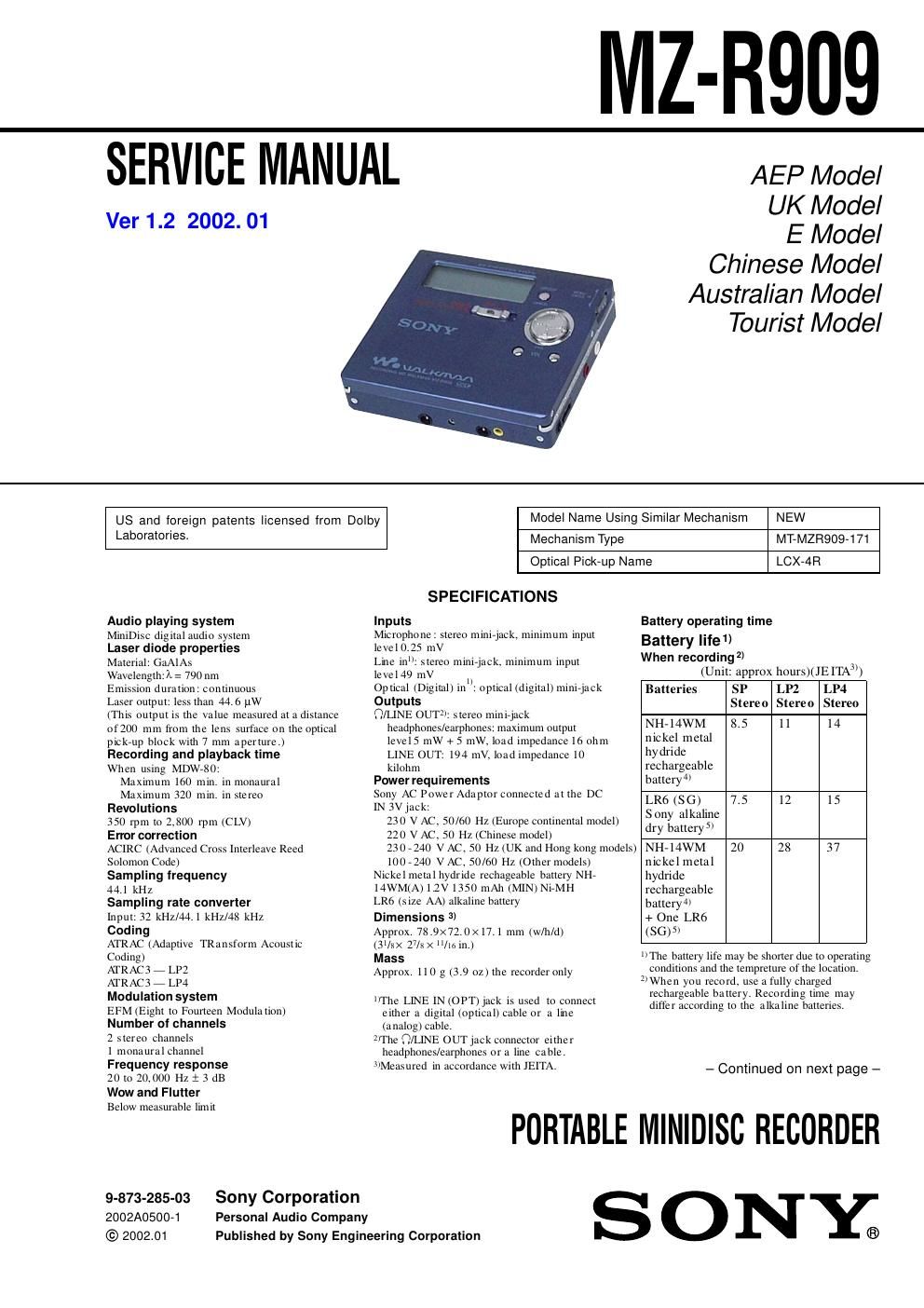
sony mz r 909 service manual

Extracted text from sony mz r 909 service manual (Ocr-read)


Page 1

2 MZ-R909 TABLE OF CONTENTS 1. SERVICING NOTES ............................................... 3 2. GENERAL ................................................................... 4 3. DISASSEMBLY 3-1. Disassembly Flow ........................................................... 5 3-2. Panel Assy, Bottom ......................................................... 5 3-3. Panel Assy, Upper Section .............................................. 6 3-4.LCD Module, Panel Assy, Upper............................ 6 3-5. MAIN Board Assy .......................................................... 7 3-6.Case Assy, Battery, MAIN Board........................... 7 3-7. Strip, Ornamental ............................................................ 8 3-8.MD Mechanism Deck (MT-MZR909-171), Chassis Assy, Set......................................................... 8 3-9. Service Assy, OP (LCX-4R) ........................................... 9 3-10. Holder Assy ..................................................................... 10 3-11. Motor, DC (Sled) (M602) ............................................... 10 3-12.Motor, DC (Spindle) (M601), Motor, DC (Over Write Head UP/DOWN) (M603)... 11 4. TEST MODE .............................................................. 12 5. ELECTRICAL ADJUSTMENTS ......................... 18 6. DIAGRAMS 6-1. Block Diagram – SERVO Section –............................... 34 6-2. Block Diagram – AUDIO Section –............................... 35 6-3. Block Diagram – KEY CONTROL/DISPLAY/ POWER SUPPLY Section –........................................... 36 6-4. Note for Printed Wiring Boards and Schematic Diagrams ....................................................... 37 6-5. Printed Wiring Board – Main Board (Component Side) –............................... 38 6-6. Printed Wiring Board – Main Board (Conductor Side) –................................. 39 6-7. Schematic Diagram – Main Board (1/4) –.................... 40 6-8. Schematic Diagram – Main Board (2/4) –.................... 41 6-9. Schematic Diagram – Main Board (3/4) –.................... 42 6-10. Schematic Diagram – Main Board (4/4) –.................... 43 6-11. IC Pin Function Description ........................................... 48 7. EXPLODED VIEWS 7-1. Panel Section ................................................................... 54 7-2. Chassis Section ............................................................... 55 7-3. MD Mechanism Deck Section (MT-MZR909-171) ....... 56 8. ELECTRICAL PARTS LIST ............................... 57 SAFETY-RELATED COMPONENT WARNING!! COMPONENTS IDENTIFIED BY MARK 0 OR DOTTED LINE WITH MARK 0 ON THE SCHEMATIC DIAGRAMS AND IN THE PARTS LIST ARE CRITICAL TO SAFE OPERATION. REPLACE THESE COMPONENTS WITH SONY PARTS WHOSE PART NUMBERS APPEAR AS SHOWN IN THIS MANUAL OR IN SUPPLEMENTS PUB- LISHED BY SONY. Design and specifications are subject to change without notice. When playing (Unit: approx.hours )(JE ITA 1)) Batteries S P StereoLP2 StereoLP4 Stere o NH-14WM n ic kel m etal hy drid e rechargeable battery 2) 24 27 3 1 LR6 (S G) Sony al kal in e dry battery 3) 34 40 4 5 NH-14WM n ic kel m etal hy drid e rechargeable battery 2) + On e LR6 (SG) 3) 64 75 8 4 1)Measured in a ccordance with the J E ITA (J ap an E lectro n ics an d In fo rm at ion Te ch n o lo g y Ind u s trie s As s o ciat ion ) s tan d a rd . 2)When using a 1 00% fu lly ch arged rechargeable ba tte ry. 3)When using a Sony LR6 (S G) STAMINA a lka line dr y batte ry (p ro duce d in Ja pan) On power sources -Us e house c u rrent, n ic kel m e tal hydride rechar geabl e batte ry, LR6 (s i ze AA) battery. or car battery. - For use in your house: For the s uppl ied batte ry char ging s ta n d, use the AC po wer adapt o r s uppl ied with th is re corder. Do not use any other AC po wer adapto r s ince it ma y cause th e re co rd er to m a lf uncti on. P o larity o f th e plug AC power adap to r (1 ) Headphones/earphones with a remote control (1) Ba tte ry ch a rging sta nd (Ass e m bly needed) (1 ) Rechargeable battery (1 ) Dry battery case (1 ) Rechargeable b a tte ry c arryin g cas e (1 ) C arrying pou ch /c a rrying case with a belt clip (1) AC plug adaptor (E xce p t Europe, China and HongKong models) (1) O p tica l cab le (1 )Supplied accessories 3)Measured in accordance with the J E ITA (J a p a n Elec tronic s a nd In fo rm a tion Technology In dust rie s Assoc ia tion) standa rd . 4)Wh e n using a 100 % fu lly charged rechargeable battery. 5)Whe n us ing a S ony LR6 (S G) STAMINA a lka line dr y battery (p roduce d in Japan). CAUTION Use of controls or adjustments or performance of procedures other than those specified herein may result in hazardous ra- diation exposure. Ver 1.1

Page 2

3 MZ-R909 NOTES ON HANDLING THE OPTICAL PICK-UP BLOCK OR BASE UNIT The laser diode in the optical pick-up block may suffer electro- static break-down because of the potential difference generated by the charged electrostatic load, etc. on clothing and the human body. During repair, pay attention to electrostatic break-down and also use the procedure in the printed matter which is included in the repair parts. The flexible board is easily damaged and should be handled with care. NOTES ON LASER DIODE EMISSION CHECK Never look into the laser diode emission from right above when checking it for adjustment. It is feared that you will lose your sight. NOTES ON HANDLING THE OPTICAL PICK-UP BLOCK (LCX-4R) The laser diode in the optical pick-up block may suffer electro- static break-down easily. When handling it, perform soldering bridge to the laser-tap on the flexible board. Also perform mea- sures against electrostatic break-down sufficiently before the op- eration. The flexible board is easily damaged and should be handled with care. OPTICAL PICK-UP FLEXIBLE BOARD SECTION 1 SERVICING NOTES - In performing the repair with the power supplied to the set, removing the MAIN board causes the set to be disabled. In such a case, fix a convex part of the open/close detect switch (S806 on MAIN board) with a tape in advance. Handle the FLEXIBLE board (overwrite head) with care, as it has been soldered directly to the MAIN board. In repairing the component side of MAIN board, connect the FLEXIBLE board (overwrite head) and the MAIN board with the lead wires in advance. (See page 7) laser-tap upper panel assy MAIN board Tape S806 FLEXIBLE board (Over write head) - Replacement of CXD2671-209GA (IC801) used in this set re- quires a special tool. - The shipment data will be cleared when the NV is reset. There- fore, change the adjusted values following the Change of Ad- justed Values immediately after the NV was reset. (See page 18) - If the nonvolatile memory was replaced on the set, the modified program data must be written to the nonvolatile memory. In such a case, write the modified data that meets the microcomputer version following the patch data rewriting procedure at the replacement of nonvolatile memory. (See page 23) Notes on chip component replacement - Never reuse a disconnected chip component. - Notice that the minus side of a tantalum capacitor may be dam- aged by heat. Flexible Circuit Board Repairing - Keep the temperature of the soldering iron around 270 ˚C dur- ing repairing. - Do not touch the soldering iron on the same conductor of the circuit board (within 3 times). - Be careful not to apply force on the conductor when soldering or unsoldering.UNLEADED SOLDER Boards requiring use of unleaded solder are printed with the lead- free mark (LF) indicating the solder contains no lead. (Caution: Some printed circuit boards may not come printed with the lead free mark due to their particular size) : LEAD FREE MARK Unleaded solder has the following characteristics. - Unleaded solder melts at a temperature about 40 ˚C higher than ordinary solder. Ordinary soldering irons can be used but the iron tip has to be applied to the solder joint for a slightly longer time. Soldering irons using a temperature regulator should be set to about 350 ˚C . Caution: The printed pattern (copper foil) may peel away if the heated tip is applied for too long, so be careful! - Strong viscosity Unleaded solder is more viscous (sticky, less prone to flow) than ordinary solder so use caution not to let solder bridges occur such as on IC pins, etc. - Usable with ordinary solder It is best to use only unleaded solder but unleaded solder may also be added to ordinary solder.