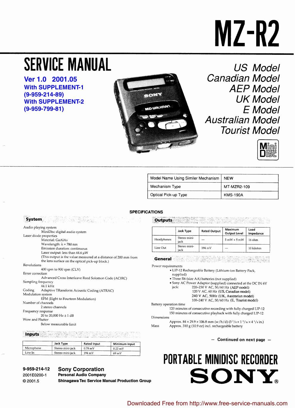
Sony mz r 2 service manual
This is the 78 pages manual for sony mz r 2 service manual.
Read or download the pdf for free. If you want to contribute, please upload pdfs to audioservicemanuals.wetransfer.com.
Extracted text from sony mz r 2 service manual (Ocr-read)
Page 1
MZ-RZ
SERVICE MANUAL
Ver 1.0 2001.05
US Model
Canadian Model
With SUPPLEMENT-1 A EP Mode]
(9-959-214-89) UK MOdeI
With SUPPLEMENT-2
(9-959-799-81) E Model
A ustra/ian Model
Tourist Model
Model Name Using Similer Mechanism NEW
Mechanism Type MT-MZR2-109
Optical Pick-up Type KMS-190A
SPECIFICATIONS
system Routines? /
AmalliléSTdu-maudiosysem mm mm. mime
Laser diode angfiega A1 A5 Headphones if?" "m" 7 5 mw + 5 mw 16 ohm
W ~
Laser outpur less man 446 ow _ ,
(This nulpul is me value measured a: a dislance onUU mm (mm General , I. ,. - . __ . _ *
ihe lens surface on the opiical pick-up block.)
Revolullons
400 rpm lo 900 rpm (CLV)
Error correclion
Advanced Cross lnlerleave Reed Solomon Code (ACIRC)
Sampllng ri-equcncy
44 1 kHz
Codmg Adaplive TRansform Acoustic Coding (ATRAC)
Modulation syslem
EFM (Eiglil lo Fourloen Modulallon)
Number of channels
2 stereo channels
Frequency response
20 to 20,000 HI. :1 dB
Wow and Flulter
Below measurable llmfl
rupees ,
lack Type Rated lnpui Minimum Input
Microphone Sleree mlnijack 0 73 mV uzz mv
Line In Stereo mlmr|afk 194 mV (:9 IIIV
9-959-214-12 Sony Corporation
2001E0200-1 Personal Audio Company
© 2001.5 ShinagawaTec Service Manual Production Group
Power requirements
- LIP-12 Rechargeable Baltery (Lithium-inn Battery Pack,
supplied)
- Three Rb (:izc AA) baneries (not supplied)
- Sony AC Power Adapmr (supplied) connecled at lhc DC 1N 5v
jack: 2207230 V AC, 50/60 Hz (AEP model)
120 V AC, 60 Hz (US, Canadian model)
240 V AC, SOHL (UK. Australian model)
100-240 V AC, 50/60 H7, (E, Tonrisl model)
Baliery operation lime
120 minules of consecutive recording with fully charged LIP-12
150 minutes of consecutive playback wilh fully charged Lllhlz
Dimensions
Approx, 84 x 299 x 1068 mm (w/h/d) (3 /3x 1 Via x4 /4 in.)
Mass Approx 310 g (109 oz) incl. rechargeable banery
- Continued on next page -
PORTABLE Mllillilsc RECORDER
S 0 NY;
Downloaded Free from http://www.free-seNice-manuals.com
Page 2
Accessories _ , 3 x v -
Optional
a LIP-12 Lithium-ion Battery Pack
- ACP-MZbOA AC Power Adaptor/ Battery Charger
. POC-MZl, POC-MZZ Optical Cable
. CPM-MZRZK Car Mount Kit
- CPA-8 Car Connecting Pack
- ECM-9Il9A, ECM-727P Stereo Microphones
- MDR-DSS, MDR-D77 Stereo Headphones
. SRS-58 Sony Active Speakers
- Recordable MDs: MDW-éfl, MDw-74
- CK-MD4 MiniDisc Carrying Case
. CK-MDln MiniDisc Filing Box
Your dealer may not handle some of the above listed accessories. Please ask
the dealer for detailed information about the accessories in your country.
us and foreign patents licensed from Dolby Laboratories Licensing Corporation,
Design and specifications are subject to change without notice.
-
Note
This Appliance Conforms WIlh arc Directive muss/EEC regarding inicrierc-nce
suppression,
For Customers in Europe
ThlS MiniDisc Recorder IS classified
as a CLASS I LASER product
The CLASS 1 LASER PRODUCT
label IS located on the bottom
m, exterior-
For Customers in Canada
This apparatus complies with the Class B limits for radio noise
emissions set out in Radio Interference Regulations.
cuss i use»: enonucr
tuoxm I LASERLAITE
KLAss l useasveamr
For Customers In the United Kingdom
This MiniDisc Recorder is classified as a
CLASS 1 LASER product.
The CLASSl LASER PRODUCT label is
located on the bottom exterior.
cuss I uses encoucr
LUDKAN I assume
KLASS i ussmpnau
The built-in battery should be replaced by qualified personnel only.
For Customers in Australia
If the supply cord of AC power adaptor is damaged the AC power adaptor
must be returned to the manufacturer or his agent for the cord to be replaced.
IN NO EVENT SHALL SELLER BE LIABLE FOR ANY DIRECT,
INCIDENTAL OR CONSEQUENTIAL DAMAGES OF ANY
NATURE, OR LOSSES OR EXPENSES RESULTING FROM ANY
DEFFECTIVE PRODUCT OR THE USE OF ANY PRODUCT.
MD W'ALKMAN" is a trademark of Sony Corporation
TABLE OF CONTENTS
Sggjign Title Base
1. SERVICING NOTE 3
2. GENERAL
Looking at the controls
Lets Start! rrrrrrrrrrrrrrrrrr
Choosing power sources
Setting the clock rrrrrrrr
Recording Irom a CD, etc.
Three ways of recording
Recording irom a microphone
Playing an MD
Playing tracks repeatedly.
Useful tips on playing an MD .
Track marking a recording
Erasing recordings ........
Connecting to a stereo system
Using in a car ..........................
Error messages
What is the MD?
co-Amoouatwb
3. DISASSEMBLY
3-1. Lid Cover Block ............................ ta
3-2, Main Board, Spindle Motor and Loading Motor . 18
3-3, Mechanism Deck (MT»MZR2-109) ............ ,
3-4. Sled Motor and Optical Pick-up Block (KSM-190A) .......... 19
4. TEST MODE
Outline .......................................................................................... 20
Setting the Test Mode
Releasing the Test Mode
Test Mode Operations
Test Mode Structure ,.
Servo Mode
Audio Mode
Mechanism Mode. .25
Power Mode ......
Table of Dot Area Dispalys .26
Other Displays
.20
Sggtlgn Title
5. ELECTRICAL ADJUSTMENTS
Laser Diode Emission Checking Precautions .........
Optical Pick-up Block (KMS-lQOA) Using Precautions
Adjusting Precautions .
Laser Power Adjustment
Offset Adjustment .......
MO Traverse Adjustment
MO P-TOC Traverse Adjustment
MO Error Rate Check
CD Traverse Adjustment
CD RF Level Adjustment
CD Error Rate Check ..
Adjusting/ Connecting Points ....................................................... 31
6. DIAGRAMS
6-1, Semiconductor Lead Layouts ............................................ 32
62, to Pin Functions
- K3601 EFM/ACIR Encoder/ Decoder (CXDZEZSR-i)
- IC602 Shock Proof Memory Controller (CXD2526AR)
ICBOS Sub System Control (MBB9133A-PFM-170) .
. ICBOS Main System Control (CXP81848-603R)
6-3. Block Diagram ..
6-4. Printed Wiring Boards.
6-5. Schematic Diagram - RF/ Servo Section h
6-6. Schematic Diagram - Process Section ~-
6-7. Schematic Diagram -~ Audio Section -
6-8. Schematic Diagram
- Micro Computer! MD Section -
6-9. IC Block Diagrams
7. EXPLODED VIEWS
7-1. Cabinet Block .....
7-2. Main Board Block .
7-3. Mechanism Deck 1 (MT-MZR2-109) .
7-4. Mechanism Deck 2 (MTeMZR2-109) .
B. ELECTRICAL PARTS LIST ..................................... 75
7.27
Downloaded Free from http://www.free-service-manualscom