Sony mz nh 600 d service manual

This is the 72 pages manual for sony mz nh 600 d service manual.
Read or download the pdf for free. If you want to contribute, please upload pdfs to audioservicemanuals.wetransfer.com.

Page: 1 / 72
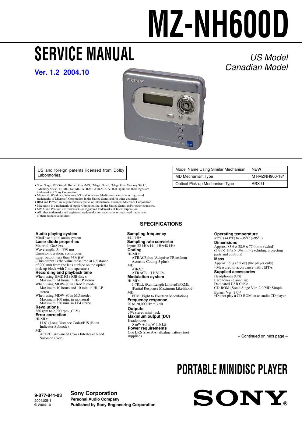
sony mz nh 600 d service manual

Extracted text from sony mz nh 600 d service manual (Ocr-read)


Page 1

MZ-NH600D

SERVICE MANUAL

Ver. 1.2 2004.10

US Model
Canadian Model

Model Name Using Similar Mechanism NEW
MT-MZNH900-1 81
Optical Pick-up Mechanism Type ABX-U

US and foreign patents licensed from Dolby
Laboratories.

MD Mechanism Type

. SomeSrage, MD Simple Burner, OpenMG. Magic Gate MagieGatc Memory so

Memory Stick". Hi-MD. Net MD. ATRAC. ATRAC3, AIRACJpIus and their logos are

rrademnrks of Sony Corporation.

. Microsoft, wtndows. Windows err and Windows Media are rmdenrarks or registered
trademarks or Microsoft Corporation in the United sures and tar other countries,

. IBM and PC/AT are registered Lrademarks oflnternttttonal dustness Machines Corporation,

. Maetntosh as a rrndemark of Apple Computer, tne. tn the United States and/or other eonnrnes.

. MMX and Pentium tue rrademarks or registered trademarks or Intel Corporation.

. All other trademarks and registered trademarks are trademarks or registemd trademarks

of men respective notders,

Audio playing system

MiniDisc digital audio system

Laser d de properties

Mate . GaAlAs

Wavelength: A = 790 nm

Emission duration: continuous

Laser output: less than 446 pW

(This output is the value measured at a distance

of 200 mm from the lens surface on the optical

pickrup block with 7 mm aperture.)

Recording and playback time

When using HMDIG (lGB dise)
Maximum 34 hours in HirLP ste 0

When using MDW»80 in HirMD mode:
Maximum 10 hours and 10 min. in HirLP
stereo

When using MDW780 in MD mode:
Maximum 160 mitt. in monaural
Maximum 320 min. in LP4 stereo

Revolutions

380 rpm to 2.700 rpm (CLV)

Error correction

Hi-MD:
LDC (Long Distance Coda/BIS (Burst
Indicator Snbcode)
D:

ACIRC (Advanced Cross Interleave Reed
Solomon Code)

SPECIFICATIONS

Sampling frequency

44,] kHz

Sampling rate converter

Input: 32 kHz/44.1 kHz/48 kHz

Coding

HirMD:
ATRAC3plus (Adaptive TRansfotm
Acoustic Coding 3 plus)

MD:

A'IRAC
ATRAC3 7 LPZ/LP4
Modulation system
HirMD:
177RLL (Run Length Limited)/PRML
(Partial Response Maximum Likelihood)
D-

EFM (Eight to Fourteen Modulation)
Frequency response
20 to 20,000 Hz : 3 dB
Outputs
Q: stereo minirjack
Maximum output (DC)
Headphones:

5 mW+5 mW(16£2)
Power requirements
One LR6 (size AA) alkaline battery (not
supplied)

Operating temperature

+5°C (+41"F) to +35°C (+95°F)
Dimensions

Approx. 83.6 X 289 X 77.0 mm (w/h/d)

(3 3/8 X 13/10 x SUE in.) (excluding projecting
parts and controls)

Mass

Approx. 99 g (3.5 oz) (the player only)
Measured in accordance with JEITA.
Supplied accessories

Headphone (US)

Earphones (Canadian)

Dedicated USB Cable

CDrROM (Sonic Stage Ver. 2.0/MD Simple
Burner Ver. 2.0V<

*Do not play a CDrROM on an audio CD player.

- Continued on next page -

PORTABLE MINIDISC PLAYER

9.877.341433 Sony Corporation
2004.10571 Personal Audio Company
©2004.10 Published by Sony Engineering Corporation

SONYa

Page 2

MZ-NH600D
Ver 1.1

Battery lite 1
When playing continuously in Hi-MD mode

Dist Iype Linear PCM Hi-Sl' Hi-LP
1013 III-MD disc Approx Approx. Apptox.

11 0 hoursii 21 5 hoIIrs3' 25 5 hoursi'
60/74/80-nunule Approx Approx. Apptox.
standard disc 9.5 hours 20 o hoursl 24 5 hoursl'

When using 11 new Sony LRo (sizc AA) alkalinc dry battcry
(produccd In Japan)

2'Mcasurcd in accordancc wrth thc JEITA (Japan Electronics and Information
Technology Industiic Association) standard.

When playing continuously in MD mode

LPZ stereo LPA stereo

Apptox, 20.5 hours Approx. 24 5 hours Approx. 270 hours

Disc type SP stereo

60/74/80-minute
standard drsc

Design and spccil'ications arc subject to change
without notice.

TABLE OF CONTENTS

1. SERVICING NOTES ............................................... 3
2. GENERAL ................................................................... 4
DISASSEMBLY

3-1. Disassembly Flow
3-2. Case (Lower) Section
3-3. MAIN Board .. ..
3-4. Case (Upper) SectIon .......................................................
3-5. Mechanism Deck Section (MT-MZNH900-l8l),

mom

\I

MD Standard Pin 7
3-6. Set Chassis Assy 8
3-7. Gera (BSA), Gera (SB) .. 8
3-8. Op Service Assy ....... .. 9
3-9 DC MOTOR SSMlSD/C-NP (SPINDLE) (M701), DC

MOTOR (SLED) (M702), DC MOTOR Unit

(Over Write Head Up/Down) (M703) ............................. 9
3- 10. Holder Assy ..................................................................... 10
4. TEST MODE .............................................................. 11
5. ELECTRICAL ADJUSTMENTS ......................... 15

6. DIAGRAMS

6-1. Block Diagram 7MD SERVO Section 7
6-2. Block Diagram 7POWER SUPPLY Section
6-3. Primed Wiring Board 7MAIN Section (1/2) 7 .
6-4. Printed Wiring Boards 7MAIN Section (2/2) 7
6-5. Schematic Diagram 7MAIN Section (1/8) 7.
6-6. Schematic Diagram 7MAIN Section (2/8) 7.
6-7. Schematic Diagram 7MAIN Section (3/8)
6-8. Schematic Diagram 7MAIN Section (4/8)
6-9. Schematic Diagram 7MAIN Section (5/8)
6-10. Schematic Diagram 7MAIN Section (6/8) 7.
6-11. Schematic Diagram 7MAIN Section (7/8) 7.
6-12. Schematic Diagram 7MAIN Section (8/8) 7.


7. EXPLODED VIEWS
7-1. Case (Lower) Section ..
7-2. Case (Upper) Section
7-3. Ch s Section ..
7-4. Mechanism Deck Section (MT-MZNH900-181)


8. ELECTRICAL PARTS LIST ................................ 46

CAUTION

Use of controls or adjustments or performance of procedures
other than those specified herein may result in hazardous radiation
exposure.

Notes on chip component replacement
- Never reuse a disconnected chip component.
0 Notice that the minus side of a tantalum capacitor may be
damaged by heat.

Flexible Circuit Board Repairing
- Keep the temperature of the soldering iron around 270 °C
during repairing.
- Do not touch the soldering iron on the same conductor of the
circuit board (within 3 times).
0 Be careful not to apply force on the conductor when soldering
or unsoldering.

UNLEADED SOLDER

Boards requiring use of unleaded solder are printed with the lead-

free mark (LF) indicating the solder contains no lead.

(Caution: Some printed circuit boards may not come printed with
the lead free mark due to their particular size)

E: LEAD FREE MARK
Unleaded solder has the following characteristics.
- Unleaded solder melts at a temperature about 40 C higher
than ordinary solder.
Ordinary soldering irons can be used but the iron tip has to be
applied to the solder joint for a slightly longer time.
Soldering irons using a temperature regulator should be set to
about 350 °C.
Caution: The printed pattern (copper foil) may peel away if
the heated tip is applied for too long, so be careful!
- Strong visc sity
Unleaded solder is more viscou-s (sticky, less prone to flow)
than ordinary solder so use caution not to let solder bridges
occur such as on IC pins, etc.
- Usable with ordinary solder
It is best to use only unleaded solder but unleaded solder may
also be added to ordinary solder.

SAFETY-RELATED COMPONENT WARNING!!

COMPONENTS IDENTIFIED BY MARK A OR DOTTED LINE
WITH MARK A ON THE SCHEMATIC DIAGRAMS AND IN
THE PARTS LIST ARE CRITICAL TO SAFE OPERATION.
REPLACE THESE COMPONENTS WITH SONY PARTS WHOSE
PART NUMBERS APPEAR AS SHOWN IN THIS MANUAL OR
IN SUPPLEMENTS PUBLISHED BY SONY.

ATTENTION AU COMPOSANT AYANT RAPPORT
A LA SECURITEI

LES COMPOSANTS IDENTIFIES PAR UNE MARQUE A SUR
LES DIAGRAMMES SCHEMATIQUES ET LA LISTE DES
PIECES SONT CRITIQUES POUR LA SECURITE DE
FONCTIONNEMENT. NE REMPLAcER CES COM- POSANTS
QUE PAR DES PIECES SONY DONT LES NUMEROS SONT
DONNES DANS CE MANUEL ou DANs LES SUPPLEMENTS
PUBLIEs PAR SONY.