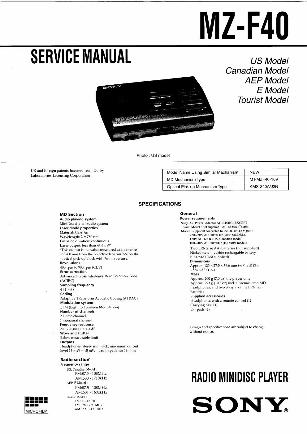
Sony mz f 40 service manual
This is the 50 pages manual for sony mz f 40 service manual.
Read or download the pdf for free. If you want to contribute, please upload pdfs to audioservicemanuals.wetransfer.com.
Extracted text from sony mz f 40 service manual (Ocr-read)
Page 1
MZ
-F40
SERVICE MANUAL
US Model
Canadian Model
Photo : US model
AEP Model
E Model
Tourist Model
MICBQEILM
US and foreign patents licensed from Dolby
Laboratories Licensing Corporation
MD Section
Audio playing system
MiniDIscdlgital audio system
Laser diode properties
Material; GaAIAs
Wavelength, t = 780 nm
Emission duration: continuous
Laser output: less than «(46 uW'
'This output is the value measured at a distance
of 200 mm from the obiective lens surface on the
optical pick-up block with 7mm aperture
Revolutions
400 rpm to 900 rpm (CLV)
Error correction
Advanced Cross lnterleave Reed Solomon Code
(ACIRC)
Sampling frequency
4 kHz
Coding
Adaptive TRansiorm Acoustic Coding (ATRAC)
Modulation system
EFM (Eight to Fourteen Modulanon)
Number of channels
2 stereo channel:
1 monaurnl channel
Frequency response
20 to 20,000 Hz x 3 dB
Wow and Flutter
Below measurable limit
Outputs
Headphones: stereo mini-lack, maximum output
level IS nlW +15 mW, load impedance 16 ohm
Radio sectiod
Frequency range
US. Canadian Model »
FM'87 5 >108MHZ
AM:. 0 l710kHz
AER E Modcl
FM:87.5 A 108MHz
AM2531 71602LHZ
Tourist Model ,
TV: I , lZCH
FM 76 0 , 90 MHz
AM 53l , 1710kHz
Model Name Using Similar Mechanism NEW
MD Mechanism Type MT-MZF40~109
Optical Pick-up Mechanism Type KMS-240A/J2N
SPECIFICATIONS
General
Power requirements
Sony AC Power Adaptor Ac-E45HGlEXCEFr
Tounsl Model : not Supplied), ACMSSA (Tounsl
Model ; supplied} connected to the DC IN 4.5V jack >
220230V AC. 50/60 Hz (AEP MODEL),
120V AC. 60HZ tUS, Canadian mod
cl).
100240V AC. 50/60Hz (ETounst modei)
Two LR6 (size AA) batteries (not supplied)
Nickel metal hydrlde recharge
BP-DMZO (not supplied)
Dimensions
tale battery
Approx 123 x 275 x796 mm (w/h/d) is x
1'/sx3/lln,)
Mass
Approx 200 g (7.0 02) the player only
Approx 293 g (103 oz) incl 3 premnstered MD,
headphones, and two Sony alkaline LRfi (SC)
batteries
Supplied accessories
Headphones with .1 remote control (I)
Carrying case (1)
Ear pads (2)
Design and specifitations are subject to change
W i thout notice.
RADIO MINIDISC PLAYER
SO
NY;
Page 2
TABLE OF CONTENTS
Specifications
1. SERVICING NOTE ........................................................ 3
2. GENERAL ........................................................................ 4
3. DISASSEMBLY
3-1. Panel Assy, Bottom Removal . 12
3-2. Lid Assy, Upper Removal ..... . 12
3-3. Main Board Removal ................... . 13
3-4. MD Mechanism Section Removal . 13
3-5. Optical Pick-up Block Assy, CLV Board Removal .. l4
3-6. MD Control Board Removal . 14
3-7. TU Board Removal ............... . IS
4. TEST MODE .................................................................. 16
5. ELECTRICAL ADJUSTMENTS ................................. 2]
For customers in Europe
CLASS 1 LASER PRODUCT
a CLASS I LASER product.
LUOKAN 1 LASERLAITE
KLASS I LASERAPPARAT
IN NO EVENT SHALL SELLER BE
LIABLE FOR ANY DIRECT.
INCIDENTAL OR CONSEQUENTIAL
DAMAGES OF ANY NATURE. OR
LOSSES OR EXPENSES RESULTING
FROM ANY DEFECTIVE PRODUCT
OR THE USE OF ANY PRODUCT.
MD WALKMAN" is a trademark of Sony
Corporation.
This Mini Disc Player is classified as
The CLASS I LASER PRODUCT
label is located on the bottom exterior.
CAUTION
Use of controls or adjustments or performance of procedures other
than those specified herein may result in hazardous radiation expo-
sure,
Flexible Circuit Board Repairing
- Keep the temperature of the soldering iron around 270°C during
repairing.
- DO not touch the soldering iron on the same conductor of the cir-
cuit board (within 3 times),
0 Be careful not to apply force on the conductor when soldering or
unsoldering.
Notes on chip component replacement
° Never reuse a disconnected chip component.
. Notice that the minus side of a tantalum capacitor may be dam-
aged by heat.
6. EXPLANATION OF ICTERMINALS
7. DIAGRAMS
7-], Block Diagram - Tuner Section -
7-2, Block Diagram - Main Section -
73. Printed Wiring Boards - Tuner Section -
7v4. Schematic Diagram - Tuner Section - ..
7-5. Printed Wiring Boards - Main Section -
7-6. Schematic Diagram - Main Section (1/3)
7-7. Schematic Diagram - Main Section (2/3) -
7-8, Schematic Diagram - Main Section (3/3) - .
8. EXPLODED VIEWS
8-], Upper Panel. Bottom Panel Section
8-2, Chassis Section
8-3. Mechanism Deck Section .
9. ELECTRICAL PARTS LIST
SAFETY-RELATED COMPONENT WARNING
COMPONENTS IDENTIFIED BY MARK A OR DOTTED LINE
WITH MARK A. ON THE SCHEMATIC DIAGRAMS AND IN THE
PARTS LIST ARE CRITICALTO SAFE OPERATION.
REPLACE THESE COMPONENTS WITH SONY PARTS WHOSE
PART NUMBERS APPEAR AS SHOWN IN THIS MANUAL OR IN
SUPPLEMENTS PUBLISHED BY SONV.
ATTENTION AU COMPOSANT AVANT RAPPORT
A LA SEOURITEI
LES COMPOSANTS IDENTIFIES PAR UNE MARouE A suR LES
DIAGRAMMES SCHEMATIOUES ET LA LISTE DEs PIECES SONT
CRITIQUES POUR LA SECURITE DE FONCTIONNEMENT. NE
REMPLACER CES COMPOSANTS OUE PAR DES PIECES SONY
DONT LES NUMEROS SONT DONNES DANS CE MANUEL OU
DANS LES SUPPLEMENTS PUELIEs PAR SONV.