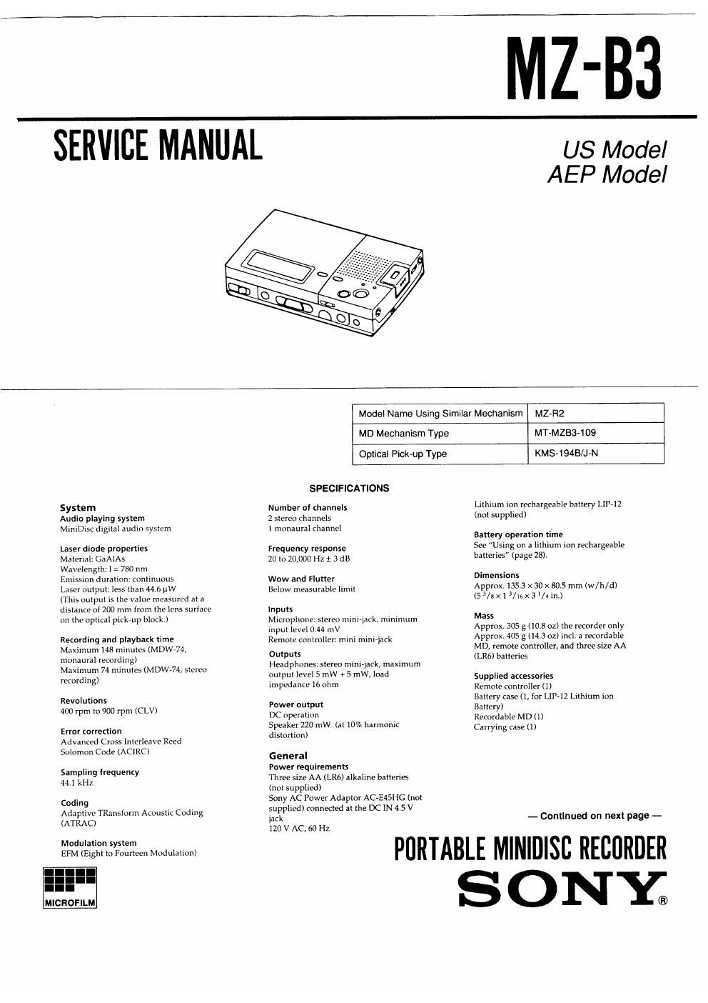
Sony mz b 3 service manual
This is the 59 pages manual for sony mz b 3 service manual.
Read or download the pdf for free. If you want to contribute, please upload pdfs to audioservicemanuals.wetransfer.com.
Extracted text from sony mz b 3 service manual (Ocr-read)
Page 1
MZ-B3
SERVICE MANUAL
US Model
AEP Model
System
Audio playing system
MmlDisc digital audio system
Laser diode properties
Material: GaAlAs
Wavelength: 1 z 780 nm
Emission duralinn: continuous
Laser output: less than 446 MW
(This output is the value measured at a
distance of 200 mm from the lens surface
on the optical pickup block.)
Recording and playback time
Maximum 148 minutes (MDWV74,
monaural recording)
Maximum 74 minutes (MDW-74, stereo
recording)
Revolutions
400 rpm to 900 rpm (CLV)
Error correction
Advanced Cross lntcrloave Reed
Solomon Code (ACIRC)
Sampling frequency
44.1 kHz
Coding
Adaptive TRansiorm Acoustic Coding
(ATRAC)
Modulation system
Em (Eight to Fourteen Modulation)
Model Name Using Similar Mechanism MZ-RZ
MD Mechanism Type
MT-MZBS-109
Optical Pick-up Type
KMS-194B/J-N
SPECIFICATIONS
Number of channels
2 stereo channels
1 mnnaural channel
Frequency response
20 to 20,000 Hz 1 3 dB
Wow and Flutter
Below measurable limit
Inputs
Microphone: stereo mini-lack, minimum
input level 0.44 mV
Remote controller: mini mini-lack
Outputs
Headphones: stereo mini~iack, maximum
output level 5 mW + 5 mW, load
impedance 16 ohm
Power output
DC operation
Speaker 220 mW (at 10% harmonic
distortion)
General
Power requirements
Three size AA (LRé) alkaline batteries
(not supplied)
Sony AC Power Adaptor AC-E45HG (not
supplied) connected at the DC IN 4.5 V
iack
120 V AC, 60 Hz
Lithium ion rechargeable battery Lll»12
(not supplied)
Battery operation time
See Using on a lithium ion rechargeable
batten'es (page 28).
Dimensions
Approx.135.3 x 30 x 805 mm (w/h/d)
(53/5x15/tnx3I/iin.)
Mass
Approx. 305 g (10.8 02) the recorder only
Approx. 405 g (14.3 oz) incl. 3 recordable
MD, remote controller, and three size AA
(LR6) batteries
Supplied accessories
Remote controller (1)
Battery case (1, for LlPiZ Lithium ion
Battery)
Recordable MD (l)
Carrying case (1)
- Continued on next page -
PORTABLE MINIDISB RECORDER
S 0 NY;
Page 2
Optional accessories
AC-E45HG AC power adaptor
LIP-12 Lithium ion rechargeable battery
ACP-MMA AC Power adaptor/
Battery charger
ECM-909A, ECM-727l, ECM-7l7 Stereo
microphones
ECM~T140, ECM-Tl 10 Monaural
microphones
MDR-E747, MDRrE535 Stereo dynamic
earphones
MDR-DSS, MDR-D33 Stereo headphones
RKCIM, RK-GIZE Line Cables
MDW-74/74A, MDW-74L/74R/74Y,
MDW-60/60A Recordable MDs
CK-MD4 MiniDisc carrying case
CK-MDIO MiniDisc filing box
" ACP-MZéCIA can only be used as a
battery charger. It cannot be used as an
AC power adaptor with this recorder.
Your dealer may not handle some of the
above listed accessories. Please ask the
dealer for detailed information about the
accessories in your country,
US and foreign patents licensed from
Dolby Laboratories Licensmg
Corporation.
Design and specifications are subject to
change without notice,
Notes on chip component replacement
- Never reuse a disconnected chip component
. Notice that the minus side of a tantalum capacitor may be
damaged by heat
Flexible Circuit Board Repairing
. Keep the temperature of the soldering iron around 270 °C
during repairing
0 Do not touch the soldering iron on the same conductor ofthe
circuit board (within 3 times).
° Be careful not to apply force on the conductor when soldering
or unsoldcring.
TABLE OF CONTENTS
Section Tit g flagg
SECTION 1. SERVICE NOTE ......................................... 3
SECTION 2 GENERAL ................................................... 4
SECTION 3. DISASSEMBLY
3-1. Upper Panel (E) Assembly and
Bottom Panel Assembly ................................................... 22
3-2 LCD Module ...................................................................... 22
3-3. Ornamental Chassis (E) Assembly,
REC Chassis Assembly
3-4. Main board, Audio Board
3-5i Mechanism Deck (MT-MZB3-109 i
36. Sled Motor and Optical Pick-up Block (KMS-194B/J7N
SECTION 4. TEST MODE
Outline .......................................................................................... 25
Setteing the Test Mode.
Exiting the Test Mode
Operations when Test Mode is Set
Structure of Test Mode l
Servo Mode ,,,,,,,,,,,,,,,,
Audio Mode a
Function Mode .
Power Supply Mode
General Adjustment Mode
SECTION 5. ELECTRICAL ADJUSTMENTS
Precautions for Laser Diode Emission Check ,,,,,,,,,,,,,,
Precautions for Using Optical Pick Up ((KMS-tQAB/J-N»
Precautions for Adjustment
Laser Power Check
MO Traverse Adjustmen .r
Low Reflection CD Traverse Adjustmen
CD Traverse Adjustment .......................
CD RF Level Check ...................................................
SECTION 6. DIAGRAMS
6-1. Circuit Boards Location ...................................................... 36
6-2 Block Diagram ......
6-3r Schematic Diagram - MD Section -
6-4 Printed Wiring Board - MD Section -
65 Printed Wiring Board - Main Section -
6-6. Schematic Diagram - Main (Servo/Process) Section -~ 49
6-7. Schematic Diagram
- Main (System Control) Section -
6-8, Schematic Diagram - Main (Audio) Section -
6»9, IC Pin Functions
0 IC501 FlF Amplifier (CXA1981AFI) .................................. 62
. ICSOS Digital signal processor, digital servo processor
(CXD2535BFI-1) ............................................
~ ICBOI ATRAC Encoder/Decoder (CXD2536R) .
- |0801 System Control (CXP819P60MR-4) ..................... 68
SECTION 7. EXPLODED VIEWS
7-1, Cabinet Section
7-2. Mic Panel Section
7-3r Main Board Section
70
71
A72
7-4, Mechanism Deck Section-1 (MT-MZB3»109) i 73
7-5 Mechanism Deck Section-2 (MT»MZB3-109) .................... 74
SECTION 8 ELECTRICAL PARTS LIST ........................ 75
_2_