Sony mhc v 11
This is the 54 pages manual for sony mhc v 11.
Read or download the pdf for free. If you want to contribute, please upload pdfs to audioservicemanuals.wetransfer.com.
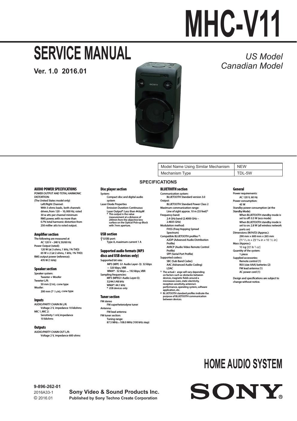
Extracted text from sony mhc v 11 (Ocr-read)
Page 1
MHC-V11
SERVICE MANUAL
Ver. 1.0 2016.01
US Model
Canadian Model
AUDIO POWER SPE(IFICATIONS
POWER ouTPuT AND TOTAL HARMoNlC
DlSTonTloN-
fine United States model only)
Len/Right channel
with 3 ohms loads, both channels
driven,fmm I20 7 I0,000 HZ rated
30 w atts per channel mlnimlim
AMS power, with no more than
0.7% total harmonlc distortion from
250 milliw ans to rated output.
Amplifier settion
The lollowing are measured at
AC i20 V - 240 V, 50/50 Hz
Power Output (rated):
120 w (at 3 ohms,l kHz, l%THD)
aszz (atz onms, l kHz l%THDl
PMS output power (relerence).
470 w (l kHz)
Speaker sedion
Speaker System:
Tweeter + Wooier
Tweeter L/R.
so mm (2 in), cone type
Woolen
200 mm (77/.in), cone type
Inputs
AUDIO/PARTY CHAlN IN UR:
Voltage 2 v, impedance IO kilonms
MIC l, MlC 2:
Sensitivity l mV, impedance
IO kilohms
Outputs
AUDIO/PARTY CHAlN ouT UR:
Voltage 2 v, impedance 600 ohms
9-896-262-01
201 6A33-1
© 2016.01
Model Name Using Similar Mechanism NEW
Mechanism Type TDL-5W
SPECIFICATIONS
Disc player settion BlU [TOOTH sedion General
System: Communication syste . Power requirements:
Compact disc and digital audio BLUEIOOTH Standard version 3.0 AC i20 V, 60 Hz
system Output: Powerconsurnption-
Laser Diode Properties BLUEIOOTH Standard Power Class 2 45 w
Emission Duratlon Continuous Maximum communication range Standby power consumption (at the
LaserOlitput" Less than new Line of sight approx. to m (33 leer)H Standby Mode):
* Thisoutput is the value
measurement ata d' ance oi
200mm from the obiective lens
suriace on the Optical Pl(k-up Black
with 7mm aperture.
053 sedion
l; (use) pom
Type A. maXimum current i A
Supported audio formats (MP3
discs and USB devites only)
Supported pit rate.
MP3 IMPE GI Audio LayerZ). 32 kbps
- 320 kpps,VoA
WMA" 32 kbps 7 I92 kbps,\/BR
Sampling frequencies:
MP3 (MPEGI Audio Layers):
3Z/44.I/48 kHz
WMA:44.I kHz
- use devices only
Tuner sedion
FM stereo
FM superneterodynetuner
Antenna.
FM lead antenna
FM tuner section:
Tuning range
87 S MHzi i080 MHz (mu kHz step)
Sony Video & Sound Products Inc.
Published by Sony Techno Create Corporation
Frequency band
2 4 GHz band (2.4000 GHz -
z 4835 GHZl
Modulation method:
FHSS lFreq Hopping Spread
Spectrum)
Compatiple ELUETDOTH pronles m
AznP (Advanced Audio Distripution
Profile)
AVRCP (Audio Video Remote Control
Profile)
SPP (Serial Port Profile)
Supported codecs.
SEC (Sup Band Codec)
AAC (Advanced Audio Coding)
tDAc
n The actual r ange Will vary depending
on iactois such as obstacles between
devices, magnetic fields around a
microwave oven, static electricity,
rxeption sensitivity, antennas
perioimance, operating system, soltware
application, etc,
BLUUOOTH Standard pmfilei lndkate the
purpose of BLUHOOTH communication
between devices.
When BLUETooTH standby mode is
set to off. 0.5 w leco mode)
When BLUETooTH standby mode is
set to on. 2.8W (all wireless network
ports on)
Dimensions (W/H/D) (Approx):
290 mm x ecu mm x 265 mm
(11 /1 in x 23 5/. in x10 VI in]
Mass (Approx).
lO kg [22 lbl 01]
Quantity oltne system.
i piece
Supplied accessories:
Remote control (ll
n03 (size AAA) batteries (2)
FM lead antenna ll)
Ac power cord (l)
Design and specifications are subject to
change without notice
HOME AUDIO SYSTEM
SONY;
Page 2
MHC-V11
License and Trademark
Notice
- MPEG Layer-3 audio coding
technology and patents licensed
from Fraunhofer IIS and Thomson.
- Windows Media is either a registered
trademark or trademark ofMicrosoft
Corporation in the United States
and/or other countries.
- This product is protected by
certain intellectual property rights
of Microsoft Corporation. Use or
distribution of such technology
outside of this product is prohibited
without a license from Microsoft or
an authorized Microsoft subsidiary.
- The BL UETOOTHm word mark and
logos are registered trademarks
owned by Bluetooth SIG, Inc. and
any use of such marks by Sony
Corporation is under license. Other
trademarks and trade names are
those of their respective owners
- The N Mark is a trademark or
registered trademark of NFC Forum,
Inc in the United States and in other
countries.
- Android is a trademark of Google
Inc
- Google Play' is a trademark of
Google Inc.
- LDACM and LDAC logo are
trademarks of Sony Corporation
- Apple , the Apple logo, iPhonel and
iPod touch are trademarks of Apple
Inc., registered in the US and other
countries.App Store is a service
mark of Apple Inc.
- "Madef or iPod"and "Made for
iPhone" mean that an electronic
accessory has been designed to
connect specifically to iPod or
iPhone, respectively,and has been
certified by the developer to meet
Apple performance standards. Apple
is not responsible for the operation
of this device or its compliance with
safety and regulatory standards.
Please note that the use of this
accessory with iPod or iPhone may
affect wireless performance
All other trademarks and registered
trademarks are of their respective
holders In this manual, TM and G7
marks are not specified.
CAUTION
The use of optical instruments with this
product will increase eye hazard.
CAUTION
Use of controls or adjustments or performance of procedures
other than those specified herein may result in hazardous radia-
tion exposure.
SAFETY CHECK-OUT
After correcting the original service problem, perform the follow-
ing safety check before releasing the set to the customer:
Check the antenna terminals, metal trim, metallized knobs,
screws, and all other exposed metal parts for AC leakage.
Check leakage as described below.
LEAKAGE TEST
The AC leakage from any exposed metal part to earth ground and
from all exposed metal parts to any exposed metal part having a
return to chas s must not exceed 0.5 mA (500 microamperes.).
Leakage current can be measured by any one of three methods.
1. A commercial leakage tester, such as the Simpson 229 or RCA
WT-540A. Follow the manufacturers instructions to use these
instruments.
2. A battery-operated AC milliammeter. The Data Precision 245
digital multimeter is suitable for this job.
3. Measuring the voltage drop across a resistor by means of a
VOM or battery-operated AC voltmeter. The limit indication
is 0.75 V, so analog meters must have an accurate low-voltage
scale. The Simpson 250 and Sanwa SH-63Trd are examples
of a passive VOM that is suitable. Nearly all battery operated
digital multimeters that have a 2 V AC range are suitable. (See
Fig. A)
To Exposed Metal
Paris on Set
A C
/ voltmeter
szw
a15pF
SE LSkQ
_T_ Earth Ground
Fig. A. Using an AC voltmeter to checkAC leakage.
SAFETY-RELATED COMPONENT WARNING!
COMPONENTS IDENTIFIED BY MARK A OR DOTTED LINE
WITH MARK A ON THE SCHEMATIC DIAGRAMS AND IN
THE PARTS LIST ARE CRITICAL TO SAFE OPERATION.
REPLACE THESE COMPONENTS WITH SONY PARTS
WHOSE PART NUMBERS APPEAR AS SHOWN IN THIS
MANUAL OR IN SUPPLEMENTS PUBLISHED BY SONY.
ATTENTION AU COMPOSANT AYANT RAPPORT
A LA SECURITE!
LES COMPOSANTS IDENTIFIES PAR UNE MARQUE A SUR
LES DIAGRAMMES SCHEMATIQUES ET LA LISTE DES
PIECES SONT CRITIQUES POUR LA SECURITE DE FONC-
TIONNEMENT. NE REMPLACER CES COMPOSANTS QUE
PAR DES PIECES SONY DONT LES NUMEROS SONT DON-
NES DANS CE MANUEL OU DANS LES SUPPLEMENTS
PUBLIES PAR SONY.