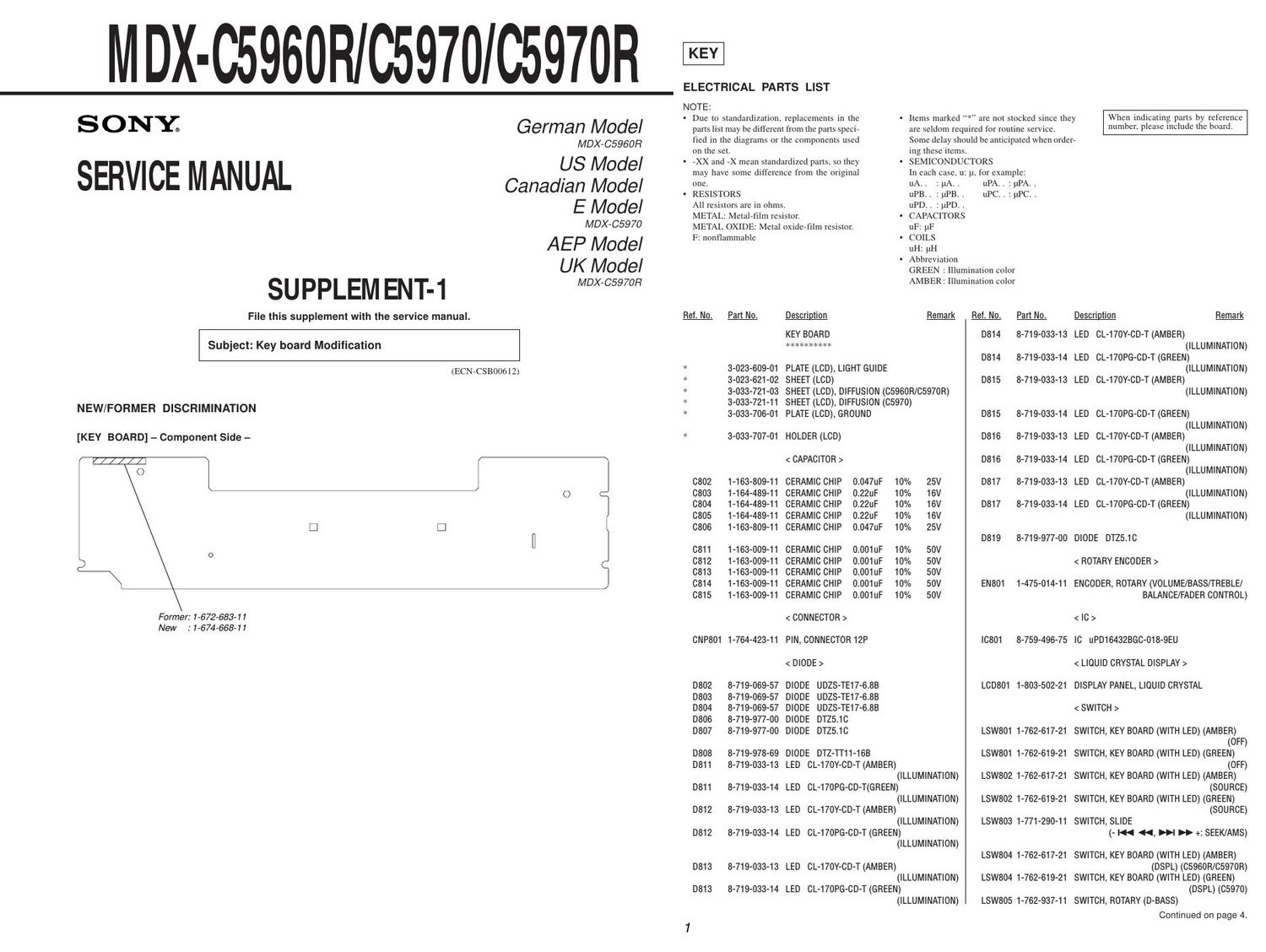
Sony mdx c 5960 r service manual
This is the 4 pages manual for sony mdx c 5960 r service manual.
Read or download the pdf for free. If you want to contribute, please upload pdfs to audioservicemanuals.wetransfer.com.
Extracted text from sony mdx c 5960 r service manual (Ocr-read)
Page 1
2 2 MDX-C5960R/C5970/C5970R PRINTED WIRING BOARD Ð KEY Board Ð ¥ Semiconductor Location (Component Side) Ref. No. Location D811 C-3 D812 B-3 D813 A-4 D814 A-2 D815 B-1 D816 C-2 D817 A-11 IC801 B-8 Q806 C-4 Q807 B-1 ¥ Semiconductor Location (Conductor Side) Ref. No. Location D802 B-12 D803 B-12 D804 B-12 D806 B-5 D807 B-5 D808 A-12 D819 B-2 Q805 B-2 Note on Printed Wiring Board: ¥X: parts extracted from the component side. ¥b: Pattern from the side which enables seeing. (The other layers' patterns are not indicated) Caution: Pattern face side:Parts on the pattern face side seen from (Conductor Side) the pattern face are indicated. Parts face side:Parts on the parts face side seen from (Component Side) the parts face are indicated.
Page 2
3 3 MDX-C5960R/C5970/C5970R Note on Schematic Diagram: ¥ All capacitors are in µF unless otherwise noted. pF: µµF 50 WV or less are not indicated except for electrolytics and tantalums. ¥ All resistors are in W and 1/4 W or less unless otherwise specified. ¥C: panel designation. ¥U: B+ Line. ¥ Power voltage is dc 14.4V and fed with regulated dc power supply from ACC and BATT cords. ¥ Voltages are taken with a VOM (Input impedance 10 MW). Voltage variations may be noted due to normal produc- tion tolerances.¥ Voltages and waveforms are dc with respect to ground under no- signal (detuned) conditions. no mark : FM ¥ Waveforms are taken with a oscilloscope. Voltage variations may be noted due to normal production toler- ances. ¥ Circled numbers refer to waveforms. ¥ Abbreviation GREEN : Illumination color AMBER : Illumination color SCHEMATIC DIAGRAM Ð KEY Board Ð