Sony mds mx 101 service manual

This is the 46 pages manual for sony mds mx 101 service manual.
Read or download the pdf for free. If you want to contribute, please upload pdfs to audioservicemanuals.wetransfer.com.

Page: 1 / 46
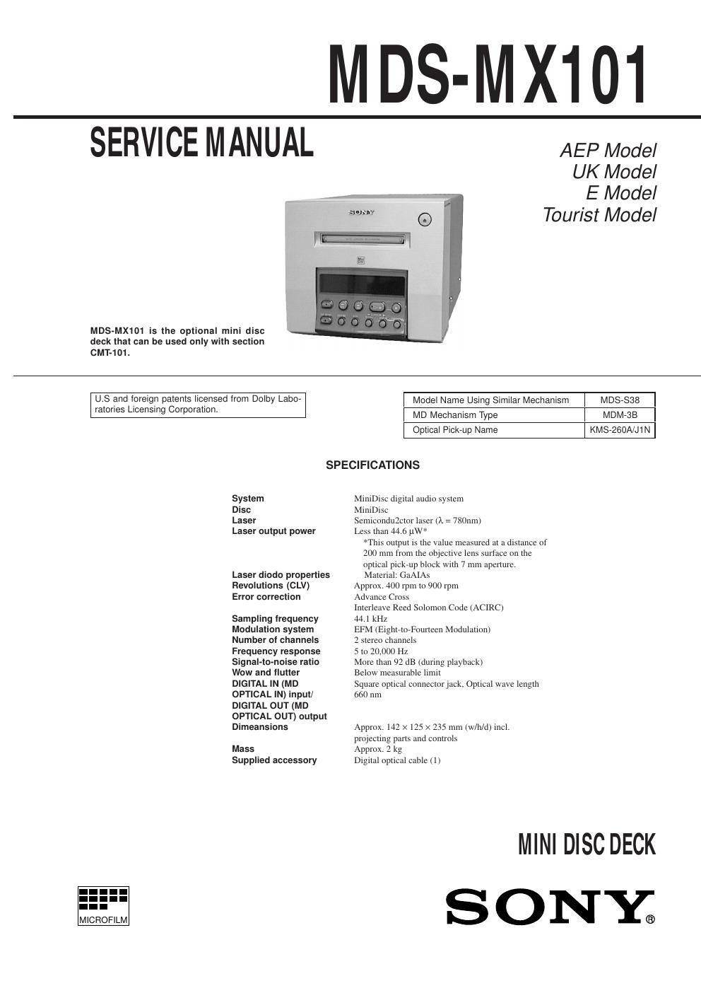
sony mds mx 101 service manual

Extracted text from sony mds mx 101 service manual (Ocr-read)


Page 1

Ñ 2 Ñ TABLE OF CONTENTS 1. SERVICING NOTES 1-1. Check Mode of Fluorescent Indicator Tube, Buttons, and LEDÕs ........................................................ 3 1-3. Extension Cable .............................................................. 3 2. GENERAL .................................................................. 4 3. DISASSEMBLY 3-1. Cover and Front Panel .................................................... 5 3-2. Mechanism Deck ............................................................ 5 3-3. Digital Board .................................................................. 5 3-4. OPJ Board, Power Board ................................................ 6 3-5. Bracket (T), (L) and (R) ................................................. 6 3-6. BD Board ........................................................................ 7 3-7. Sub Chassis ..................................................................... 7 3-8. Shutter Assembly ............................................................ 8 3-9. Over Write Head ............................................................. 8 3-10. Slider Complete Assembly ............................................. 9 4. TEST MODE........................................................ 10 5. ELECTRICAL ADJUSTMENTS ......................... 13 6. DIAGRAMS 6-1. Circuit Boards Location ................................................. 18 6-2. Block Diagram ............................................................... 19 6-3. Printed Wiring Boards Ð MD Mechanism Deck Section Ð ................................. 22 6-4. Schematic Diagram Ð MD Mechanism Deck Section Ð ................................. 25 6-5. Schematic Diagram Ð Digital Section Ð ......................... 31 6-6. Printed Wiring Boards Ð Digital Section Ð ..................... 35 6-7. Schematic Diagram Ð Display Section Ð ........................ 38 6-8. Printed Wiring Boards Ð Display Section Ð .................... 41 6-9. Printed Wiring Boards Ð Power Section Ð ...................... 43 6-10. Schematic Diagram Ð Power Section Ð .......................... 45 6-11. IC Block Diagrams ......................................................... 47 6-12. IC Pin Functions ............................................................. 49 7. EXPLODED VIEWS ................................................ 56 8. ELECTRICAL PARTS LIST ................................. 60 CAUTION Use of controls or adjustments or performance of procedures other than those specified herein may result in hazardous radiation exposure. This appliance is classified as a CLASS 1 LASER product. The CLASS 1 LASER PRODUCT MARKING is located on the rear exterior. Laser component in this product is capable of emitting radiation exceeding the limit for Class 1. The following caution label is located inside the unit. NOTES ON HANDLING THE OPTICAL PICK-UP BLOCK OR BASE UNIT The laser diode in the optical pick-up block may suffer electrostatic break-down because of the potential difference generated by the charged electrostatic load, etc. on clothing and the human body. During repair, pay attention to electrostatic break-down and also use the procedure in the printed matter which is included in the repair parts. The flexible board is easily damaged and should be handled with care. NOTES ON LASER DIODE EMISSION CHECK The laser beam on this model is concentrated so as to be focused on the disc reflective surface by the objective lens in the optical pick- up block. Therefore, when checking the laser diode emission, observe from more than 30 cm away from the objective lens.Notes on chip component replacement ·Never reuse a disconnected chip component. ·Notice that the minus side of a tantalum capacitor may be damaged by heat. Flexible Circuit Board Repairing ·Keep the temperature of the soldering iron around 270 ûC during repairing. ·Do not touch the soldering iron on the same conductor of the circuit board (within 3 times). ·Be careful not to apply force on the conductor when soldering or unsoldering. CAUTION Danger of explosion if battery is incorrectly replaced. Replace only with the same or equivalent type recommended by the manufacturer. Discard used batteries according to the manufacturerÕs instructions.

Page 2

Ñ 3 Ñ SECTION 1 SERVICING NOTES 1-1.CHECK MODE OF FLUORESCENT INDICATOR TUBE, BUTTONS, AND LEDS Setting the Check Mode: This mode is activated by inserting the AC power cord of the PFJ- 1 power supply jig (or HCD-101) into AC wall outlet while pressing the REC button and the CHARACTER button. When this mode started, the fluorescent indicator tube and LEDs are all turned on. 1-1-1. Button Check Mode (Key Check) When the respective buttons (12 buttons are used in total) are pressed while all tube and LEDs are turned on, the display area which corresponds to the pressed button, is turned off. This mode ends by pressing the CD SYNC button at last. 1-1-2. Fluorescent Indicator Tube Check Mode (Segment Check) When the button check mode ends, [Segment Check] appears and the respective dots of the 12-digit, 5 x 7 segment fluorescent tube are lit every other dot. This mode ends by pressing the CD SYNC button at last. 1-1-3. Fluorescent Indicator Tube Check Mode (Scroll Check) When the segment check ends, [Scroll Check] appears. When the SCROLL button is pressed, the displayed letter scrolls to the left one letter after another. When all letters are scrolled, [end] appears. Press YES button to return to the normal operating mode. 1-2. EXTENSION CABLE The two types of extension cable are available during repair of this set. The extension cable (part code no. J-2501-086-A) is available to connect CN103 of the BD board and CN200 of the DIGITAL board. The extension cable (part code no. J-2501-103-A) is available to connect CN102 of the BD board and CN201 of the DIGITAL board. CN102 CN103 CN200CN201 Extension Cable (J-2501-086-A) Extension Cable (J-2501-103-A) Ñ BD board (Conductor side) Ñ Ñ DIGITAL board (Component side) Ñ SERVICENG NOTE ¥ Supplying power during servicing This equipment cannot operate without using a separate power supply. Connect the machine to the HCD-101. To apply power set the SYSTEM POWER switch of HCD-101. When other units are not available use the PFJ-1 power supply jig. When using the PFJ-1, press the POWER switch of the conversion board to turn on the power. [Connection Diagram] PFJ-1 (Power Supply jig) POWER SWConnector Cable 17P (Supplied with set) FH-E939, 838, 737, MHC-6600, 5600, CDP/TC Conversion Board (J-2501-144-A) *when checking the recording function of MDS-MX101, select any function other than MD using the Function key of the conversion board before check.SYSTEM CONTROL Set Power Function