Sony mdr if 8000 service manual

This is the 20 pages manual for sony mdr if 8000 service manual.
Read or download the pdf for free. If you want to contribute, please upload pdfs to audioservicemanuals.wetransfer.com.

Page: 1 / 20
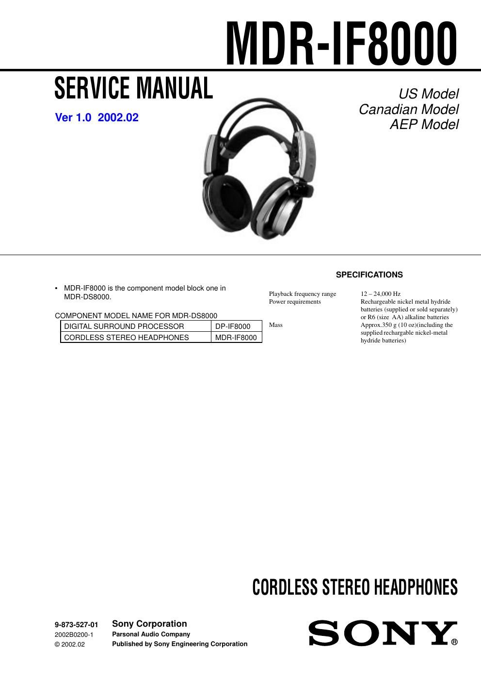
sony mdr if 8000 service manual

Extracted text from sony mdr if 8000 service manual (Ocr-read)


Page 1

SERVICE MANUAL

Ver 1.0 2002.02

NIDR-IFOOOO

US Model
Canadian Model
AEP Model

~ MDFHFBOOO is the component model block one in

MDR-DS8000.

COMPONENT MODEL NAME FOR MDR-DSBOOO
DIGITAL SURROUND PROCESSOR DP-IF8000
CORDLESS STEREO HEADPHONES MDR-IF8000

9-873-527-01 Sony Corporation
2002802004 Personal Audio Company

© 2002.02 Published by Sony Engineering Corporation

SPECIFICATIONS

Playback frequency range 12 - 24,000 Hz

Power requirements Rechargeable nickel metal hydride
batteries (supplied or sold separately)
or R6 (size AA) alkaline batteries

Mass Approx.350 g (10 oz)(including the
supplied rechargable nickel-metal
hydride batteries)

CORDLESS STEREO HEADPHONES

SONY;

Page 2

MDR-IF8000

Notes on chip component replacement

- Never reuse a disconnected chip component.

- Notice that the minus side of a tantalum capacitor may be
damaged by heat.

Flexible Circuit Board Repairing

- Keep the temperature of soldering iron around 270°C during
repairing.

- Do not touch the soldering iron on the same conductor of the
circuit board (within 3 times).

- Be careful not to apply force on the conductor when soldering
or unsoldering.

Repair MDR-IF8000 and DP-IFSOOO in a pair.

TABLE OF CONTENTS

1. GENERAL .......................................................................... 2

2. DISASSEMBLY
271. Hanger (R) .....................................
2-2. VOL Board, RXl Board, RX2 Board

273r PDl Board .................. ..................................... 4
274. Driver ASSY (SP31) (R-ch Sec on),

DriverASSY (SPil) (L7ch Section) ..................................... 4
2-5 Hanger (L), Headband (R) ASSY, Headband (F) ASSY,

SW Board
3. ELECTRICAL ADJUSTMENTS ................................. 6
4. DIAGRAMS

471. Block Diagrams ..............................
4-2. Printed Wiring Board 7 RX] Section 7 .
473. Schematic Diagram 7 RXl Section 7
474. Printed Wiring Board 7 RX2 Section 7
475 Schematic Diagram 7 RX2 Section (1/2) 7
4-6 Schematic Diagram 7 RX2 Section (2/2) 7

5. EXPLODED VIEWS

5]. Driver Section...
572. Hanger Section .

6. ELECTRICAL PARTS LIST ........................................ 16

SECTION 1

GENERAL

LOCATING THE CONTROLS

This section is extracted from
instruction manual.

Inlrared sensor

There are infiarcd sensors in two
locations on both sides.

Battery case
Press and litt up the lid to open it. This
battery case 15 for the supplied
rechargeable batteries and R6 (size AA)
alkaline batteries only.

Sell-adjusting band
The headphones automatically turn on
when you put on the headphones.

E POWER indicator
By pulling up the selfiadjustirlg band, the
indicator lights red when battery power
is sufficient.

E] RESET button (See page 21 for
details)
Use to reset the location information of
the head tracking function.

@ HEAD TRACKING switch (See page
21 lor details)
To activate the head tracking function
switch it to ON when the output mode of
the processor is set to VIRTUAL (other
than OFF).

VOL (Volume) control
Use to adjust the volume.

Ear pad (right)

E] Ear pad (lelt)