Sony mdr if 5 k service manual

This is the 20 pages manual for sony mdr if 5 k service manual.
Read or download the pdf for free. If you want to contribute, please upload pdfs to audioservicemanuals.wetransfer.com.

Page: 1 / 20
sony mdr if 5 k service manual

Extracted text from sony mdr if 5 k service manual (Ocr-read)


Page 1

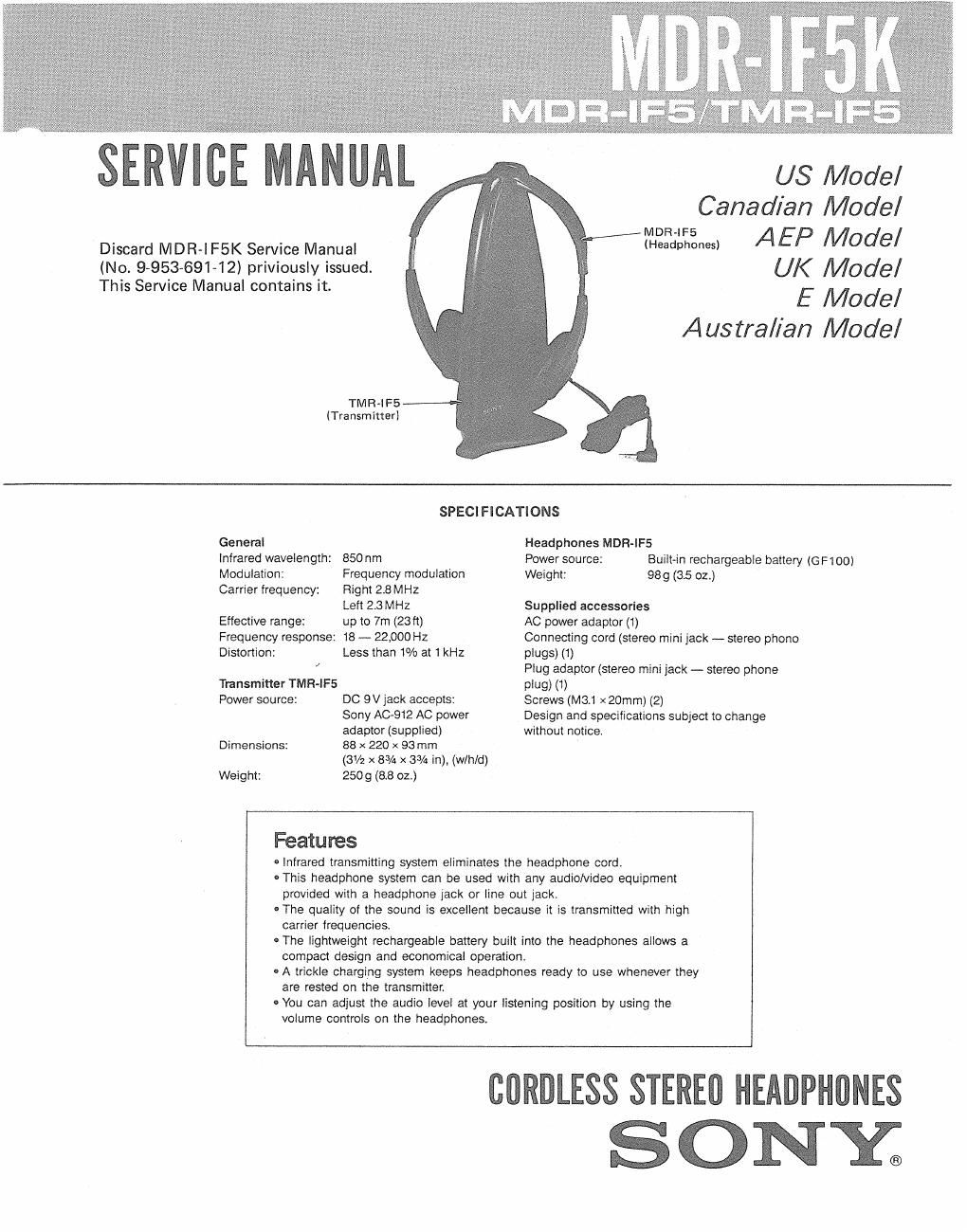
SERVICE MANUAL

Discard MDR-l F5K Service Manual
(No. 9953-69142) priviously issued.
This Service Manual contains it.

US Model
Canadian Model
mega-Liam) AEP MOOIQ/
UK Model

E Model
Austral/an Model


TMR-lFE
(Transmitter)

SPECIFICATIONS

General Headphones MDR-IFS
Infrared wavelength: 850nm Power source: Built-in rechargeable battery (GF100)
Modulation: Frequency modulation Weight: 989 (3.5 02,)
Carrier frequency: Flight 2.8 MHz

Left 2.3 MHz Supplied accessories
Effective range: up to 7m (23 ft) AC power adaptor (1)
Frequency response: 18 - 22,000 Hz Connecting cord (stereo mini jack - stereo phono
Distortion: Less than 1% at tkHz plugs) (1)

Plug adaptor (stereo mini jack - stereo phone

Transmitter TMR-IFS plug) (1)
Power source: DC 9V jack accepts: Screws (M31 x 20mm) (2)

Sony A0912 AC power Design and specifications subject to change

adaptor (supplied) without notice.
Dimensions: 88 x 220 x 93 mm

(3V2 x 83/4 x 3% in), (w/hld)
Weight: 2509 (8.8 02.)

Features

0 Infrared transmitting system eliminates the headphone cord.

- This headphone system can be used with any audio/video equipment
provided with a headphone jack or line out jack.

0 The quality of the sound is excellent because it is transmitted with high
carrier frequencies.

0 The lightweight rechargeable battery built into the headphones allows a
compact design and economical operation,

- A trickle charging system keeps headphones ready to use whenever they
are rested on the transmitter.

- You can adjust the audio level at your listening position by using the
volume controls on the headphones.

CORDLESS STEREO HEADPHONES
SONY®

Page 2

MDK-IF5K

MDR-lF5/TMvaF5

SECTION 1
GENERAL

Pads ldentmcali n
g

-

Charging inuicanm


lnlrarea emmevs

Inlmreo sensals

Conrad pins

Quick chalge buncn

Dc IN av (00 mnal
pom lnpul] jack

Audlo inpux m

,-- lnlramc sensor

m SWIILI'I

Head band

comm holes

Valume conlruls

Ear pads

I lon ng the Transmitter

The diagram below mummy: me mmimale ellective range 01
me mam rays emmod (mm ma lransrniner, Posmon (he lransmn.

ler so mat your lislening area is w'nhln me elleclive vange,

mm
fl 9 fl

-»4
j 35~

awn mules!" 3

Side View

Q g

lvansrrlmer

SAFETY»RELATED COMPONENT WARNING

COMPONENTS IDENTIFIED BY MARK A OR DOTTED
LINE WITH MARK A ON THE SCHEMATIC DIAGRAMS
AND IN THE PARTS LIST ARE CRITICAL TO SAFE
OPERATION. REPLACE THESE COMPONENTS WITH
SONV PARTS WHOSE PART NUMBERS APPEAR AS
SHOWN IN THIS MANUAL OR IN SUPPLEMENTS PUB-
LISHED BY SONY.

The mlwea rays w. nu
oeneflsIe walls a openue
glass, merelcre lhe hem-
phones mus1 be used m
"in 519m" area D! me

ATTENTION AU COMPQSANT AVANT RAPPORT
A LA SECURITE!

LEs COMPOSANTS IDENTIFIES PAR UNE MAROUE [A
sun LES DIAGRAMMES scuéMATlOUEs ET LA LISTE
DES PIECES SONT cmnouEs POUR LA sEcuanE
DE FONCTIONNEMENT. NE REMPLACER ces com-
POSANTS QUE PAR DES PIECES SONY DONT LEs
NUMERos SONT DONNEs DANS CE MANUEL 0U
DANS LES SUPPLEMENTS PUBLlEs PAR soNv.