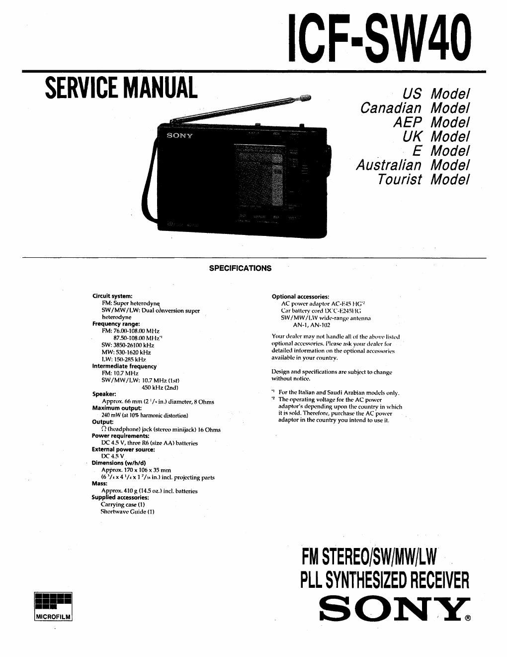
Sony icf sw40 service manual
This is the 22 pages manual for sony icf sw40 service manual.
Read or download the pdf for free. If you want to contribute, please upload pdfs to audioservicemanuals.wetransfer.com.
Extracted text from sony icf sw40 service manual (Ocr-read)
Page 1
ICF-SW40
SERVICE MANUAL
US Model
Canadian Model
AEP Model
UK Model
, t E Model
Australian Model
Tourist Model
SPECIFICATIONS
Circuit system:
FM: Super hetemdymxn
SW/MW/LW: Dual Ct version super
hetemdyne
Frequency range:
FM: 76.004081 MHZ
8750-10800 M} In"
SW: 3850-26I00 kHz
MW: 530-1620 kHz
LW: 150285 kHz
Intermedlare frequency
FM: I0.7 M Hz
SW/MW/I.W: 10.7 MHz (Isl)
450 kHz (2nd)
Speaker:
Approx. 66 mm (2 l« in.) diameter, 8 Ohms
Maximum output:
2-10 mW (at IU'X» harmonic distortion)
Output:
9 (headphone) jack (stereo miniiack) l6 Ohms
Power requirements:
DC 4.5 V, three R6 (size AA) batteries
External power source:
DC 4.5 V
. Dimensions (wlhld)
Appmx. I70 x106 x 35 mm
(6 *l. x 4 lth 1 7/m in.) incL projecting parts
Mass:
Approx. 410 g (14.5 oz.) incl. batteries
Supplied accessories:
Carrying case (ll
Shortwave Guide (1)
Optional accessories:
AC pmver adapter AC +15 HG"
Car battery curd LXC- AJSI IL?
SW / MW/ LW wide-range antenna
AN-I , AN-iUZ
Your dealer mav not handle all M the above listed
nptiunal accesst cs. IIeasbe ask your dealer [or
detailed intunnatiun on the optimal accessories
available in your muniry.
Desiin and specifications are subject to Change
without nulicer
" For the ltaIian and Saudi Arabian models unly.
'1 The operating voltage for the AC power
adapturs depending upon the country in which
it is sold» Therefore, purchase the AC power
adapter in the munh'y you intend to use it
FM STEREO/SWIMW/LW ,
PLL SYNTHESIZED RECEIVER
SONY;
Page 2
Section
S
S
1.
' Location of Controls
TABLE OF CONTENTS
Title
pecifications - -
ervicing Note-
GENERAL
Operating the Radio-
Setting the Standby ~
Setting the Sleep Timer -~
Using Other Functions
Setting the Clock ~-
éxo'xoxtnisc'o
DISASSEMBLY
2,]. Cabinet (Rear) Removal ..................
2-2. Key Board and Main Board Removal --
-7
ELECTRICAL ADJUSTMENTS ................................ 8
EXPLANATION OF IC TERMINALS -------------------- 11
DIAGRAMS
5-1. Printed Wiring Boards
5-2. Schematic Diagram -
EXPLODED VIEW ................................................ 22
ELECTRICAL PARTS LIST ................................... 23
SERVICING NOTE
Flexible Clncult Board Rapnlrlng
0 Keep the temperature of the soldering iron around
270'C during repairing.
0 Do not touch the soldering iron on the same con-
ductor of the circuit hoard(within 3 times).
0 Be careful not to apply force on the conductor
when soldering or unsoldering.
Notn on chlp component replacement
0 Never- reuse a disconnected chip component.
0 Notice that the minus side of a tantalum capacitor
may be damaged by heat.
Page
Features
- FM sweo/SW/MW/LW portable receiver with
worldwide band coverage
' Quartz-controlled ILL (Phase Locked Loop)
synthesizer system min; a microcomputer for
easy pinpoint tuning
I Preeetting of up to 20 stations for quick tuning
- Dual timer standby function to receive your
favorite broadcast at the desired time
I Sleep timer to turn the radio off automatically
after a specified number of minutes
' FM stereo reception through stereo headphones
(not supplied)
0 HOW TO CHANGE THE CERAMIC FILTERS
This model is used two ceramic filters of CFZ, CF4.
You must use same type of color marked ceramic filters in
order to meet same specifications.
Therefore, the ceramic filter must change two pieces together
since its supply two pieces in one package as a spare parts.
m Mark £2332.
Ix; red 10.70MHz
CF2. 4 blue 10.67MI-iz
orange 10.73MH2
I I I black 10.64MHZ
white 10.76MHz