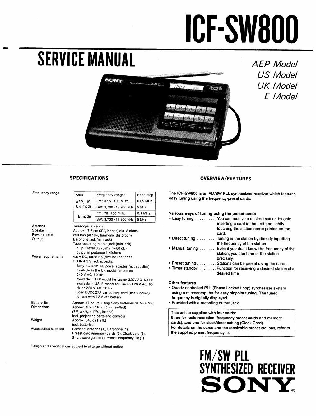
Sony icf sw 800 service manual
This is the 32 pages manual for sony icf sw 800 service manual.
Read or download the pdf for free. If you want to contribute, please upload pdfs to audioservicemanuals.wetransfer.com.
Extracted text from sony icf sw 800 service manual (Ocr-read)
Page 1
ICE-SWBIIII
SERVICE MANUAL
AEP Model
US Model
UK Model
E Model
SPECIFICATIONS
Frequency "99 Area Frequency ranges Scan step
AEP, U5. FM: 37 5-106 MHz 0.05 MHz
UK model sw: 3,700- 17,900 kHz 5 kHz
FM: 76408 MHz 0.1 MHz
E model
SW: 3.700 - 17.900 kHz 5 kHz
Antenna Telescopic antenna
Speaker Approx; 7.7 cm (Sls inches) dia. 8 ohms
Power output 250 row (at 10% harmonic distortion)
Output Earphone jack (miniiack)
Tape recording output jack (minijack)
output level 0.775 mV (- 60 as)
output impedance 1 kilohms
4.5 V DC. three R6 (size AA) batteries
DC IN 45 V jack accepts:
Sony AGDRM AC power adaptor (not supplied)
available in the UK model for use on
240 V AC. 50 Hz
available in AEP model for use on 220V AC, 50 Hz
available in US, E model for use on 120 V AC, 60
Hz or 220 V AC. 50 Hz
Sony DOC-127A car battery cord (not supplied)
for use with 12 V car battery
Power requirements
Battery tile Approx. 17 hours. using Sony batteries sumo (NS)
Dimensions Approx. 159 x116 x 45 mm (w/h/d)
(71; x 45/,5 x 1 31,, inchesi
incl. projecting parts and controls
Weight Approx. 540 g (1.2 lb)
incl. batteries
Compact antenna (1), Earphone (1).
Preset cards/memory cards (3), Clock card (1),
Short wave guide (1), Preset frequency list (1)
Accessories supplied
Design and specifications subject to change without notice.
OVERVIEW/ FEATURES
The ICFSWEOD is an FM/SW PLL synthesized receiver which features
easy tuning using the frequency-preset cards.
Various ways of tuning using the preset cards
- Easy tuning .......... You can receive a desired station by only
inserting a card in the unit and lightly
touching the station name printed on the
card.
0 Direct tuning ......... Tuning in the station by directly inputting
the frequency of the station.
- Manual tuning ........ Even it you dont know the frequency of the
station. you can tune in the station
precisely.
. .Stations can be preset using the cards.
. .Function for receiving a desired station at a
desired time.
- Preset tuning . . . .
. Timer standby . . .
Other teatures
~ Quartz controlled PLL (Phase Locked Loop) synthesizer system
using a microcomputer for easy pinpoint tuning. The tuned
frequency is digitally dlsplayed.
~ Provided with a recording output jack.
This unit is supplied with tour cards:
three for radio reception (frequency-preset cards and memory
cards), and one for clock/timer setting (Clock Card).
For details on the cards and the receivable preset stations, refer to
the supplied preset lrequency list.
FM/ SW PLL
SYNTHESIZED RECEIVER
SONY;
Page 2
lCF-SW8OO
Notes on chip component replacement
0 Never reuse a disconnected chip component.
0 Notice that the minus side of a tantalum capacitor may be damaged by heat.
TABLE OF CONTENTS
Section EL? Lagg
SERVICING NOTES
0 Notes on Replacing Light Sensor
RPR-359F (IC101 to IC104) .......................... 3
0 Notes on Replacing ROM IC (1C5) .................. 3
0 Preset Frequency List .............................. 4
AE6 : Germany ................................ 4
5AE7 : Austria ...........................
3AE7 : Swiss ...........................
2AE7 : Scandinavia .................
6AE7 : Portugal .......................
7AE7 : lntemational Sales Divisron in Europe
E
US
UK
E
1. GENERAL
0 Location of Controls .............................. 12
0 Setting the Clock .................................. 13
0 Listening to the Radio ............................ 14
0 To Preset the Desired Station Using
the Memory Card ................................ 16
0 To Turn the Radio On at the Desired Time ........ 17
2. ELECTRICAL ADJUSTMENTS .................... 18
3. IC TERMINAL DESCRIPTION
3-1. Terminal Description of [lPDl7150-605'22 (1C2). . . .20
3.2. Function of BR93CS46F (ICS) Terminal .......... 21
4. DIAGRAMS
4-1. Printed Wiring Boards (New Type) .............. 23
4-2. Schematic Diagram (New Type) .................. 27
4-3. Schematic Diagram (Former Type) .............. 31
4-4. Printed Wiring Boards (Former Type) ............ 35
4-5. Semiconductor Lead Layouts .................... 39
5. EXPLODED VIEW ................................ 40
6. ELECTRICAL PARTS LIST ...................... 41
._2__