Sony icf sw 7600 service manual

This is the 27 pages manual for sony icf sw 7600 service manual.
Read or download the pdf for free. If you want to contribute, please upload pdfs to audioservicemanuals.wetransfer.com.

Page: 1 / 27
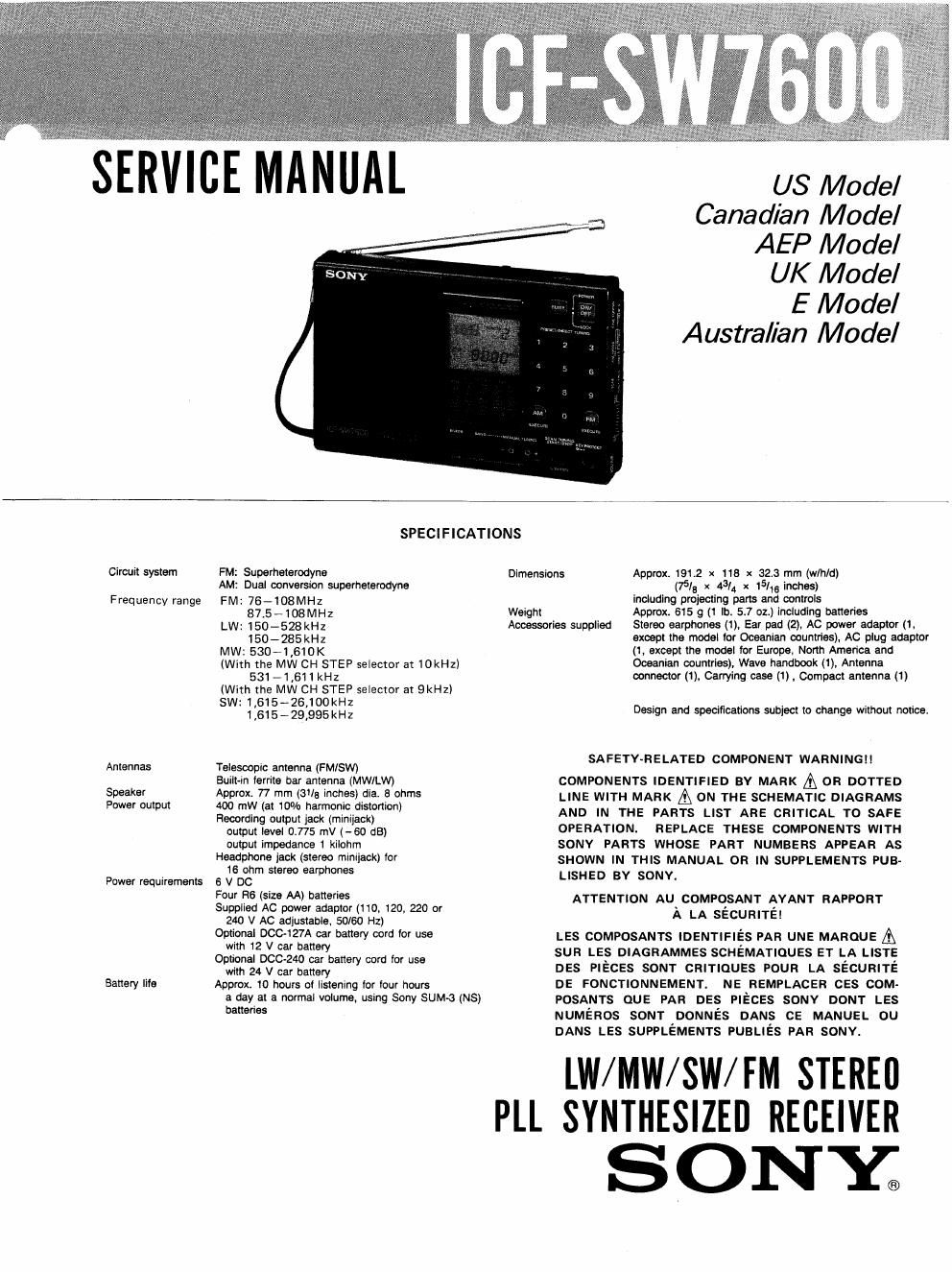
sony icf sw 7600 service manual

Extracted text from sony icf sw 7600 service manual (Ocr-read)


Page 1

SERVICE MANUAL

U8 Model
Canadian Model
AEP Model

UK Model

E Model
Australian Model

Circuit system

Frequency range

Antennas

Speaker
Power output

Power requirements

Battery life

SPECIFICATIONS

FM: Superheterodyne

AM: Dual conversion superheterodyne

FM: 76-108MHz
87.5-108MH1

LW:150-528kHz
150-285kHz

MW: 530-1,610K

(With the MW CH STEP selector at 10kHzI
531 - 1 ,611 kHz

(With the MW CH STEP selector at 9kH2)

SW: 1,615-26,100kHz
1,615-29,995kHz

Telescopic antenna (FM/SW)

Built-in ferrite oar antenna (MWILW)

Approx. 77 mm (3'13 inches) die. 3 ohms

400 mW (at 10% harmonic distortion)

Recording output jack (minijack)
output level 0,775 mV (-60 dB)
output impedance 1 kilohm

Headphone jack (stereo mimjack) lor
16 ohm stereo earphones

6 V DC

Four R6 (size AA) batteries

Supplied AC power adaptor (110, 120, 220 or
240 V AC adjustable, 50/60 Hz)

Optional DOC-127A car battery cord for use
with 12 V car battery

Optional DCC<240 car battery cord for use
with 24 V car battery

Approx. 10 hours of listening icr four hours
a day at a normal volume. using Sony SUM-3 (NS)
batteries

Dimensions Approx. 191.2 x 113 x 32.3 mm (w/h/d)
(75/8 x 431 x 15/16 inches)
including projecting pans and controls
Weight Approx. 615 g (1 lb. 5.7 oz.) including batteries

Accessories supplied

Stereo earphones (1). Ear pad (2), AC power adaptor (1,

except the model for Oceanian countries). Ac plug adaptor

(1, except the model for Europe, North America and
Oceanian countries), Wave handbook (1), Antenna
connector (1), Carrying case (1) , Compact antenna (1)

Design and specifications subject to change without notice.

SAFETY-RELATED COMPONENT WARNING! !

COMPONENTS IDENTIFIED BY MARK A 0R DOTTED
LINE WITH MARK [Q ON THE SCHEMATIC DIAGRAMS
AND IN THE PARTS LIST ARE CRITICAL TO SAFE
OPERATION. REPLACE THESE COMPONENTS WITH
SONY PARTS WHOSE PART NUMBERS APPEAR AS
SHOWN IN THIS MANUAL OR IN SUPPLEMENTS PUB-
LISHED BY SONY.

ATTENTlON Au_c0MPQSANT AYANT RAPPORT
A LA secuané!

LES COMPOSANTS IDENTIFIES PAR UNE MAROUE A
sun LES DIAGRAMMES SCHéMATIoues ET LA LISTE
DES PIECES SONT CRITIQUES POUR LA SECURITE
DE FONCTIDNNEMENT. NE REMPLACER ces COM-
POSANTS QUE PAR DES PIECES souv DONT LES
NUMEROS SONT DONNES DANS ca MANUEL ou
DANS LES SUPPLEMENTS PUBLIES PAR SONY.

LW/MW/SW/ FM STEREI]

PI.I. SYNTHESIZEI] RECEIVER

SONY;

Page 2

IC F-SW7600

TABLE OF CONTENTS

F EATU R ES

- An LW/MWISWIFM stereo receiver with worldwide band coverage.
0 Quartz controlled PLL (Phase Locked Loop) synthesizer system
using a microcomputer lor easy pinpoint tuning. The tuned

- SSE (Single side band) can be received.

- Provided with a recording output and a remote control iack.
Connecting the unit to the optional Sony TOM-27 cassette-comer
using these jacks, you can start recording programs at a desired

Tuning in the station by inputting the irequency oi
the station directly,

Even ii you dont know the irequency of the
station, you can tune in the station precisely,

An automatic searching of a station.

Section Title Page
SPECIFICATIONS -- . $5.1"7J'rfiiifcg'ngi'rii'fi'ifiif: tuning.
Features ........
SECTION 1. GENERAL
1-1. Location and Function of Controls ~~~~~~~~~~~~ 3
1-2. How to Set the Clock ------ time.
13~ Direct Tuning """"""" . Various ways of tuning
14. 80031 Tuning """"""" Direct tuning
1-5- Scan Tuning ................
1-6. Preset Tuning ................. .. 3 Manual mine --
1-7. How to Tune in Precisely ----- scan tuning
SECTION 2. OUTLINE Preset tuning .,

2-1. Outline of the C-MOS Digital-tuning Systal
10201. uPD17156-558-22 and LLPDl'IlSG-SBQ-ZZ

0 Other features

. Outline of the Station-selection --------- 7 Tlmef 38th -~
. Description on the Terminals ~~ ------ 8 sump mar
, Imtxal-state Setting -------------- l-l
. Muting-output Timings ..................... 11 Power sources ,
. Segments and Cannons of Liquid-crystal
Display panel (LCDZOl) .................... 13
2-1-6. Relationship of LCD (LCDZUI) Segments
taLSl pins ~- ---13
SECTION 3, DISASSEMBLY- 14
SECTION 4. ELECTRICAL ADJUSTMENTS ------------ 14
SECTION 5. DIAGRAMS
5-1. 10 Block Diagram ~ 17
5-2. Printed Wiring Boards - 18
5-3. Schematic Diagram -' ' 21
SECTION 6. EXPLODED VIEWS ' ' 24
SECTION 7. ELECTRICAL PARTS LIST ----- 26


0 Classification by frequency coverage

Up to 10 stations can be preset ior button-touch
tuning.

The function to receive a desired station at a
desired time
Turning the radio on automatically in 65 minutes

Three different power sources: tntemal batteries,
house current, car battery.

With the supplied AC power adaptor. any AC
power source is available.

freq.
FM AM

Type
TYPE 1 75 -105MHz 150 - 29995KHz
TYPE 2 87.5-108MHz 150 - 29995YHz
TYPE 3 150 - 2851(Hz
(Saudi Arabia) 510 531 - 2510mm:
TYPE 4 50 - 285kiiz
87.5-108MH2 531- 1602kHz
(Italian) 3850 - 26100Kilz