Sony icf sw 20 service manual

This is the 10 pages manual for sony icf sw 20 service manual.
Read or download the pdf for free. If you want to contribute, please upload pdfs to audioservicemanuals.wetransfer.com.

Page: 1 / 10
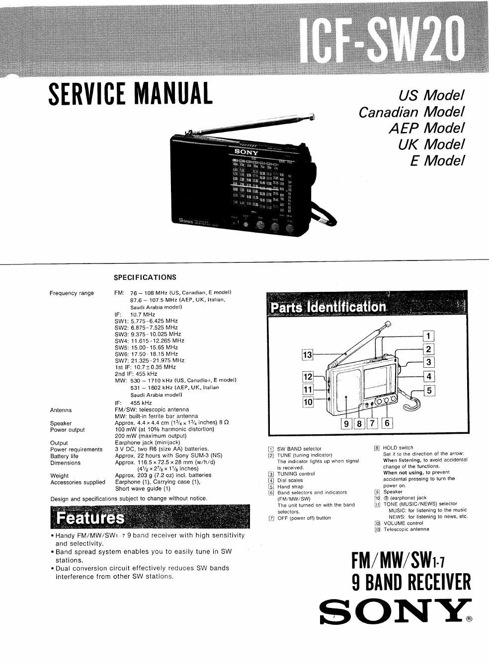
sony icf sw 20 service manual

Extracted text from sony icf sw 20 service manual (Ocr-read)


Page 1

SERVICE MANUAL

US Model

Canadian Model

AEP Model
UK Model
E Model

Frequency range

Antenna

Speaker
Power output

Output

Power requirements
Battery tile
Dimensions

Weight
Accessories supplied


and selectlyity.

- Band spread system enables you to easily tune in SW

stations.

- Dual converslon circuit effectively reduces SW bands

Design and specifications subject to change without notice.

SPECIFICATIONS

FM: 76 - 108 MHZ (US, Canadian, E model)
87.6 7107.5 MHz (AEP, UK, |ta|iar|,

Saudi Arabia model)
[F: 10.7 MHz
SW1: 5.775-6.425 MHZ
SW2: 6375-7525 MHZ
SW3: 9.375, 10.025 MHZ
SW4: 1161542265 MHZ
SW5: 15.00-15.65 MHZ
SW6: 17.50718.15 MHZ
SW7: 21325-21375 MHZ
1st IF: 10.720135 MHZ
2nd IF: 455 kHz

MW: 530 - 1710 kHz (US, Canadian, E model)
531 - 1602 kHz [AEP, UK, Italian

Saudi Arabia model)
IF: 455 kHz
FM/SW: telescopic antenna
MW: built-in ferrite bar antenna

Approx. 4.4 x 4.4 cm (13/1 x13/4 inches) 8 n
100 mW (at 10% harmonic distortion)

200 mW (maximum output)
Earphone jack (minijack)
3 V DC. two H6 (size AA) batteries.

Approx. 22 hours with Sony SUM-3 (NS)
Approx. 116.5 x 72.5 x 28 mm (w/h/d)

(4V2 x 27/3 x 1%, inches)

Approx. 203 g (7.2 oz) inclo batteries

Earphone (1), Carrying case (1),
Short wave guide (1)

0 Handy FM/MW/SWIVI 9 band receiver with high sensitivity

Interference from other SW stations.

dentiiiéaiiqiil'

E SW BAND selector

[get TUNE (tuntng Indicator)
The Indicator lights up when signal
is received,

at TUNING control

[11 Dial scales

El Hand strap

[,6] Band selectors and indicators
(FM/MW/SW)
The unit turned on wit» the band
selectors.

[fl OFF (power or!) button

it

RE
Lt'él

HOLD switch

Set it 10 the direction 01 [he arrow:

When tlstenlng, to avoid occidental

change or the luncttons.

When not using. to prevent

accidental pressing to turn the

power on.

Speaker

(9) learphone) jack

TONE (MUSIC/NEWS) selector
mustc. lor listening to the music
NEWS tor listening to news, etc.

VOLUME control

Telescopic antenna

FM/ MW/SWl-i
9 BAND RECEIVER

SONY;

Page 2

ICF-SWZO
SECTION 1

an" DISASSEMBLY

FRONT AND REAR CABINET

Note: Follow the disassemblv procedure in the nemerical order given.

0 +BTP2 x 8 (2 pcs.) front cabinet tuning shaft

+ P 20 rear cabinet
.tuning knob 0 ET 2 x

claw
claw

Be careful
not to break off
claws at 7 portions.

DIAL POINTER SETTING

o 1.7 x 3 G dial scale plate
0 M1.4 x 3

0 Match the hole with 7N
l


setting the variable
capacitor gear gap in
the arrow Q direction. 6 switch board

0 tuning belt

0 Turn the
variable capacitor
fully counterclockwise.

(D

center of ®
scratched lines I -

9 First, turn the tuning shaft fully in the arrow 6
direction. Move only the dial pointer in the
arrow Q direction and set it on the center of the
scratched lines on the dial scale plate. Apply suitable
locking compound to 6 portion.