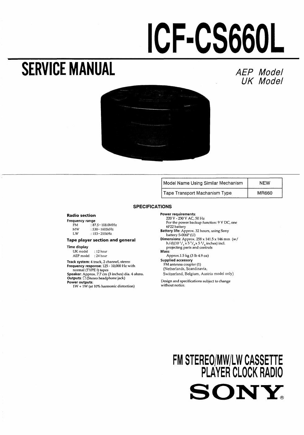
Sony icf cs 660 l service manual
This is the 20 pages manual for sony icf cs 660 l service manual.
Read or download the pdf for free. If you want to contribute, please upload pdfs to audioservicemanuals.wetransfer.com.
Extracted text from sony icf cs 660 l service manual (Ocr-read)
Page 1
ICF-CS660L
SERVICE MANUAL
AEP Model
UK Model
Model Name Using Similar Mechanism NEW
Tape Transport Machanism Type MR660
SPECIFICATIONS
Radio se ion Power requirements:
Frequency :nge 220 V - 230 V AC, 50 Hz
_ For the power backup function: 9 V DC, one
FM .87.5-108.0MHZ 6F22 battery
MW S30- IGOSKHZ Battery life: Appmx. 32 hours, using Sony
LW : 153- 255kHz bane, WP (U)
Ta e la er section and eneral Dimensions: Approx. 258 x1415 x146 mm (w/
P P y g h/d)(10IX55/Ax53/inches)incl.
Time display projecting parts and controls
UK model . l2 hour Mass:
AE? model :24 hour
Track system: 4 hack, 2 channel, stereo
Frequency response: 125 - 10,000 Hz with
normal (TYPE l) tapes
Speaker: Approx 7.7 cm (3 inches) dis. 4 ohms.
Outputs: 1'? (Stereo headphone jack)
Power outputs:
1W + ]W (at 10% harmonic distortion)
Approx,l.5 kg (3 lb 4.9 oz)
Supplied auessory
FM antenna coupler (1)
(Netherlands, Scandinavia.
Switzerland, Belgium. Austria model only)
Design and specifications subiect to change
without notice.
FM STEREO/MW/LW CASSETTE
PLAYER CLOCK RADIO
SONE
Page 2
TABLE OF CONTENTS
Specifications .................................................................. 1
1. GENERAL
Location and Function of Controls --------------------------------- 4
2. DISASSEMBLY
2-1. Cabinet (top) and Cabinet (front) Removal ------------------ 5
2.2, Main Board Removal .............................................. 5
3. DIAL POINTER INSTALLATION ------------------------------- 6
4. ELECTRICAL ADJUSTMENTS
4-1. Mechanical Adjustments-e
4-2. Electrical Adjustments
5. DIAGRAMS
5-1. Printed Wiring Boards
S»2. Schematic Diagram
6. EXPLODED VIEWS
6-1. Cabinet (Front) Section (1) ~
~17
6-2. Cabinet (Front) Section (2) ~ 18
6-3. MD Section ....................................................... 19
7_ ELECTRICAL PARTS LIST ...................................... 20
Flexible Circuit Board Repairing
0 Keep the temperature of the soldering iron around
270°C during repairing.
0 Do not touch the soldering iron on the same conduc-
tor of the circuit board (within 3 times).
0 Be careful not to apply force on the conductor when
soldering or unsoldering.
Notes on chip component replacement
I Never reuse a disconnected chip component.
0 Notice that the minus side of a tantalum capacitor
may be damaged by heat.
SAFETY-RELATED COMPONENT WARNINGI!
COMPONENTS IDENTIFIED BY MARK A OR DOTTED
LINE WITH MARK A ON THE SCHEMATIC DIAGRAMS
AND IN THE PARTS LIST ARE CRITICAL TO SAFE
OPERATION. REPLACE THESE COMPONENTS WITH
SONY PARTS WHOSE PART NUMBERS APPEAR AS
SHOWN IN THIS MANUAL OR IN SUPPLEMENTS PUB-
LISHED BY SONY.