Sony icf c 295 service manual

This is the 9 pages manual for sony icf c 295 service manual.
Read or download the pdf for free. If you want to contribute, please upload pdfs to audioservicemanuals.wetransfer.com.

Page: 1 / 9
sony icf c 295 service manual

Extracted text from sony icf c 295 service manual (Ocr-read)


Page 1

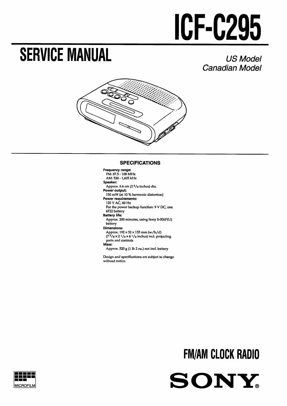
_|CF-0295

SETWICETVIANUAL _ Mode,

Canadian Model

SPECIFICATIONS

Frequency range:
FM: 87.5 . 108 MHz
AM: 530 ~ 1,605 kHz
Speaker:
Approx. 6.6 cm (2 5/ inches) dia.
Power output:
150 mW (at 10 16 harmonic distortion)
Power requirements:
121) V AC, 60 Hz
For the power backup function: 9 V DC, one
6F22 battery
Bakery life:
Approx. 200 minutes, using Sony MENU)
battery
Dimensions:
Approx. 192 x 52 x15 mm (w/h/d)
(7 5/3 x 2 1/ x 6 Vii inches) incl. projecting
parts and controls
Mass:
Approx, 520 g (1 lb 2 oz.) no! incl. battery

Design and specifications are subject to change
without notice.

FM/AM CLOCKRADIO

Page 2

HOW TO CHANGEDTHE CERAMIC FILTERS

This model is used two ceramic filters of CF2 and CF3.

You must used same type of color marked ceramic filters in order
to meet same specifications.

Therefore, the ceramic filter must changed two pieces together
since it's supply two pieces in one package as a spare parts.

Mark Center frequency
CF2
red 10.70 MHz
"ak blue 10.67 MHz
orange 10.73 MHz
CF3 black 10.64 MHz
white 10.76 MHz

SAFETY-RELATED COMPONENT WARNING"

COMPONENTS IDENTIFIED BY MARK A OR DOTTED
LINE WITH MARK A ON THE SCHEMATIC DIAGRAMS
AND IN THE PARTS LIST ARE CRITICAL TO SAFE
OPERATION. REPLACE THESE COMPONENTS WITH
SONY PARTS WHOSE PART NUMBERS APPEAR AS
SHOWN IN THIS MANUAL OR IN SUPPLEMENTS PUB-
LISHED BY SONY.

SAFETY CHECK-OUT

After correcting the original service problem, perform the follow-
ing safety check before releasing the set to the customer:

Check the antenna terminals, metal trim, metallized knobs,
screws, and all other exposed metal parts for AC leakage.

Check leakage as described below.

LEAKAGE TEST

The AC leakage from any exposed metal part to earth ground and

from all exposed metal parts to any exposed metal part having a

return to chassis, must not exceed 0.5 mA (500 microampers.).

Leakage current can be measured by any one of three methods.

1. A commercial leakage tester, such as the Simpson 229 or RCA
WT-540A. Follow the manufacturers instructions to use these
instruments.

2. A battery-operated AC milliammeter. The Data Precision 245
digital multimeter is suitable for this job.

3. Measuring the voltage drop across aresistor by means of a VOM
or battery-operatedAC voltmeter. The limit indication is 0.75
V, so analog meters must have an accurate low-voltage scale.
The Simpson 250 and Sanwa SH-63Trd are examples of a pas-
sive VOM that is suitable. Nearly all battery operated digital
multimeters that have a 2 V AC range are suitable. (See Fig. A)

To Exposed Metal
Parts on Set

AC
/ voltmeter
(0.75 V)

g 1.5 kn
E_ Earth Ground
Flg. A. Uslng an Ac voltmeter to cheokAC leakage.

0.15 |.l.F

ATTENTION AUCOMPOSANT AYANT RAPPORT
A LA SECURITE!

LES COMPOSANTS IDENTIFIES PAR UNE MAROUE A
sun LES DIAGRAMMES SCHEMATIOUES ET LA LISTE
DES PIEcEs SONT cnITIoUEs POUR LA SEOURITE
DE FONCTIONNEMENT. NE HEMPLACER cs5 com-
POSANTS QUE PAR DES PIECES SONY DONT LES
NUMEROS SONT DONNES DANS CE MANUEL ou
DANS LES SUPPLEMENTS PUBLIES PAR SONY.