Sony icf c 26 service manual
This is the 9 pages manual for sony icf c 26 service manual.
Read or download the pdf for free. If you want to contribute, please upload pdfs to audioservicemanuals.wetransfer.com.
Extracted text from sony icf c 26 service manual (Ocr-read)
Page 1
ICF-CZB
SERVICE MANUAL AEP Model
lfijfii E E iii UK Model
@II @IIEJ
SPECIFICATIONS
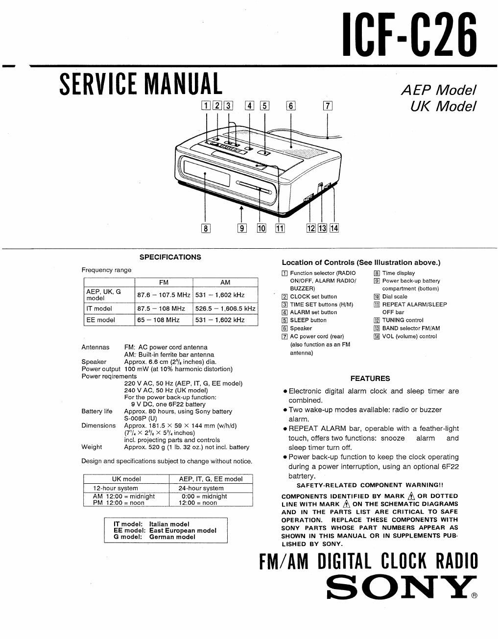
Location of Controls (See Illustration above.)
Frequency range 33 Function selector (RADIO Time display
FM AM ONIOFF, ALARM RADIO/ El Power back-up battery
AEP UK G BUZZER) compartment (bottom)
model I 87s T 1075 MHZ 531 ' 1.602 kHZ ' CLOCK set button Dial scale
TIME SET buttons (HIM) (fl) REPEAT ALARM/SLEEP
IT model 875 - 108 MHZ 5265 - 1.6065 kHz E, ALARM set button OFF bar
EE model 65 ~ 108 MHz 531 - 1,602 kHz IE] SLEEP button @ TUNING control
1E Speaker BAND selector FM/AM
AC power oord (rear) VOL (volume) control
Antennas FM: AC power cord antenna (5° "mm as an FM
AM: Built-in ferrite bar antenna antenna)
Speaker Approx. 6.6 cm (25/. inches) dia.
Power output 100 mW (at 10% harmonic distortion)
Power reqirements
220 V AC. 50 Hz (AEP. IT, G, EE model) FEATURES
240 V AC, 50 HZ (UK model) 0 Electronic digital alarm clock and sleep timer are
For the power backup function: combined
9 V DC. one 6F22 battery '
Battery me Approx. 30 hours. using Sony battery 0 Two wake-up modes available: radio or buzzer
_ S-ooeP (U) alarm.
Dme$'°"s QEf'fix'zlffsi gag) mm (WW) a REPEAT ALARM bar, operable with a feather-light
A s t .
incl. projecting parts and controls touch, offers two functions: snooze alarm and
Weight Approx. 520 g (1 lb. 32 02.) not incl. battery sleep timer turn off.
0 Power back-up function to keep the clock operating
Design and specifications subject to change without notice. , , . 4 .
during a power Interruption, using an optional 6F22
UK model AEP, IT, G, EE model barter)
12_hoursysem 24-hoursystem SAFETY-RELATED COMPONENT WARNINGI!
AM 12:00 = midnight 0:00 = midnight COMPONENTS IDENTIFIED BY MARK & OR DOTTED
PM 120° = "00 12100 = 00" LINE WITH MARK A ON THE SCHEMATIC DIAGRAMS
AND IN THE PARTS LIST ARE CRITICAL To SAFE
n. model. Italian model OPERATION. REPLACE THESE COMPONENTS WITH
5E mode}: Eastgumpean mode, SONV PARTS WHOSE PART NUMBERS APPEAR As
G model: German model SHOWN IN THIS MANUAL OR IN SUPPLEMENTS PUB-
LISHED By SONY.
FM/AM DIGITAL CLOCK RADIO
SON'Y.
Page 2
SECTION 1
GENERAL
1-1. MODEL IDENTIFICATION 1-2. MAIN BOARD REMOVAL
" ma "5" Labe' 0 Turn TUNING knob fully clockwise.
Carved on lower cabinet 9 Release {00k
9 Remove main board pressing down TUNING knobl
Note: When installing main board, align shaft of VOL
knob with a hole of adjustable resistor.
SONY.
FM/AM 2BANDS
MODEL no. ICF-CZS
0
/ @\ main board
adjustable
. resistor
AEP, IT, G, EE model: AC: 220«230 V 50 Hz 5W
UK model: AC: 240 V 50 Hz 5W
VOL knob
9 tuning knob
SAFETY STANDARD UK ONLY
Dress Power Cord
® Push to groove completely.
(E) Wond once around boss.
© Dress between boss & rib. ' \
71 ®
®
[1:0 ©
I\
\\,
,\n1
\I
W
power cord
cabine! (lower)