Sony icf c 203 service manual

This is the 16 pages manual for sony icf c 203 service manual.
Read or download the pdf for free. If you want to contribute, please upload pdfs to audioservicemanuals.wetransfer.com.

Page: 1 / 16
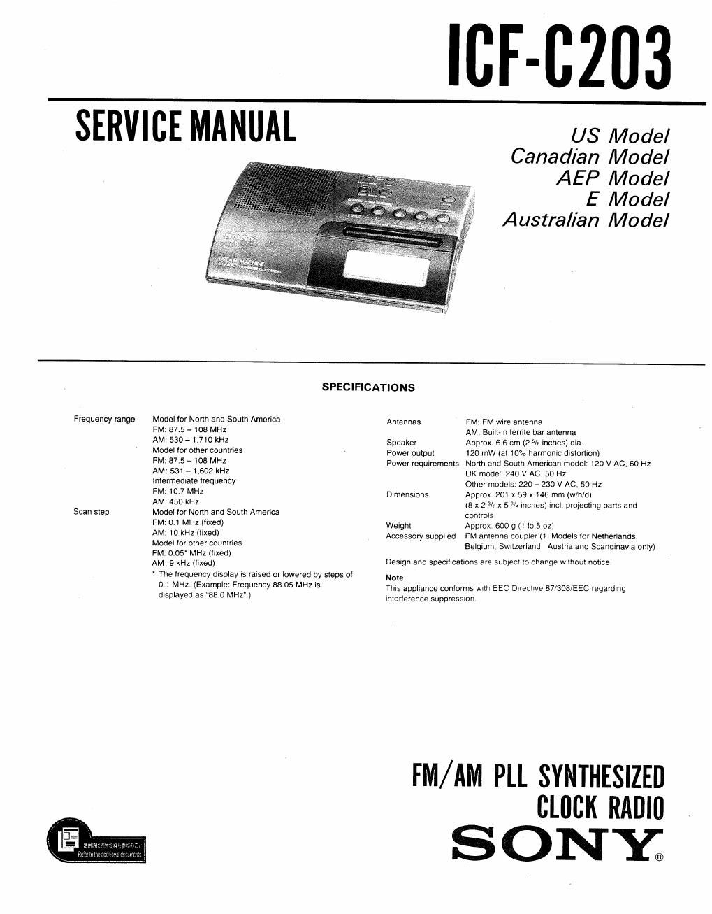
sony icf c 203 service manual

Extracted text from sony icf c 203 service manual (Ocr-read)


Page 1

"if-6203

SERVICE MANUAL

US Model
Canadian Model
AEP Model

E Model
Austral/an Model

Frequency range

Scan step

SPECIFICATIONS

Model for North and South America

FM: 87.5 - 108 MHZ

AM' 530 - 1,710 kHz

Model lor other countries

FM, 87.5 - 108 MHZ

AM: 531 - 1,602 kHz

Intermediate frequency

FM: 10.7 MHz

AM: 450 kHz

Model for North and South America

FM 0.1 MHz (Itxed)

AM: 10 kHz (llxed)

Model lor other countries

FM: 005' MHZ (fixed)

AM. 9 kHz (fixed)

The lrequency display is raised or lowered by steps of
0.1 MHz, (Example. Frequency 88.05 MHz Is
displayed as "880 MHZ")

Antennas FM: FM wire antenna

AM: Built-in ferrite bar antenna
Speaker Approx. 6.6 cm (2 5/3 Inches) dia,
Power output 120 mW (at 10% harmonic distortion)

Power requirements North and South American model' 120 V AC, 60 Hz
UK model, 240 V AC. 50 HZ
Other models 220 - 230 V AC. 50 Hz

DimenSIons Approx, 201 x 59 x 146 mm (w/h/dj
(8 x 2 3/8 x 5 3/: II'ICIIGSI incl projecting parts and
controls

Weight Approx 600 g (t to 5 oz)

Accessory supplied FM antenna coupler (1. Models tor Netherlands.
Belgium, Swrtzerland. Austna and Scandinavia only)

Deslgn and specrllcailons are subject to change Without notice,

Note
Thls appliance conforms wtth EEC Directive 87/308/EEC regarding
interterenoe suppressron

FM/ AM PLL SYNTHESIZED
CHICK RADIO

SONY.

Page 2

ICF-C203

SAFETY CHECK-OUT

After correcting the original service problem,
perform the following safety check before releasing
the set to the customer:

Check the antenna terminals, metal trim, metallized
knobs, screws, and all other exposed metal parts for
AC leakage. Check leakage as described below.

LEAKAGE TEST

The AC leakage from any exposed metal part to
earth ground and from all exposed metal parts to any
exposed metal part having a return to chassis, must
not exceed 0.5 mA (500 microampers). Leakage
current can be measured by any one of three
methods.

I. A commercial leakage tester, such as the
Simpson 229 or RCA WT-540A. Follow the
manufacturers instructions to use these instru-
ments.

2. A battery-operated AC milliammeter. The Data
Precision 245 digital multimeter is suitable for
this job.

3. Measuring the voltage drop across a resistor by
means of a VOM or battery-operated AC volt-
meter. The limit indication is 0.75 V, so
analog meters must have an accurate low-
voltage scale. The Simpson 250 and Sanwa
SH-63Trd are examples of a passive VOM that
is suitable. Nearly all battery operated digital
multimeters that have a 2 V AC range are
suitable. (See Fig. A)

To Exposed Metal
Part: on Set

0.15M: [ gum / fostmeter
. (0.75v/
._l

T Earth Ground

r

Fig. A. Using an AC valtmetm to check AC leakage.

MODEL IDENTIFICATION
- Specification Label ---

SONY.

FM/AM 2 BANDS

'/////////////////

MODEL NO. ICE-0203

///////////A

US, 0ND model: AC : 120V BOHZ 3W
AUS model: A01240VN50HZ 3W
SAEC, AEO, AEZ, IT, E modele01220-230VNSOH2 3W

0ND : Canadian model
IT: Italian model
AUS:Auslralian model
AEC, SAEczNoth European model

SAFETY-RELATED COMPONENT WARNING! I

COMPONENTS IDENTIFIED BV MARK A 0R DOTTED
LINE WITH MARK A ON THE SCHEMATIC DIAGRAMS
AND IN THE PARTS LIST ARE CRITICAL TO SAFE
OPERATION. REPLACE THESE COMPONENTS WITH
SONY PARTS WHOSE PART NUMBERS APPEAR AS
SHOWN IN THIS MANUAL OR IN SUPPLEMENTS PUB-
LISHED BY SONY.

ATTENTION AU COMPOSANT AVANT RAPPORT
A LA SECURITEI

LES COMPOSANTS IDENTIFIES PAR UNE MARQUE A
sun LEs DIAGRAMMES SCHEMATIOUES ET LA LISTE
DES PIECES soNT CRITIQUES POUR LA SECURITE
DE FONCTIONNEMENT. NE REMPLACER CES COM»
POSANTS ouE PAR DES PIECES sonv DONT LEs
NUMERos SONT DoNNEs DANS CE MANUEL ou
DANS LES SUPPLEMENTS PUBLIEs PAR soNv.