Sony icd 37 service manual

This is the 18 pages manual for sony icd 37 service manual.
Read or download the pdf for free. If you want to contribute, please upload pdfs to audioservicemanuals.wetransfer.com.

Page: 1 / 18
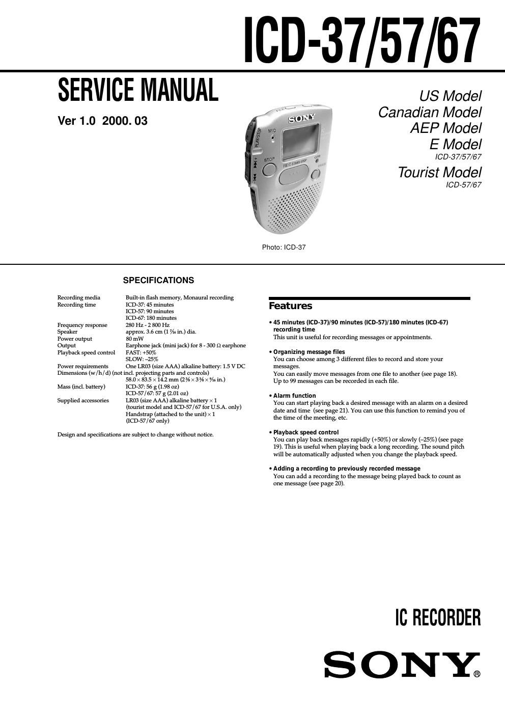
sony icd 37 service manual

Extracted text from sony icd 37 service manual (Ocr-read)


Page 1

– 2 – TABLE OF CONTENTS 1. SERVICING NOTES ............................................... 2 2. GENERAL ................................................................... 3 3. DISASSEMBLY ......................................................... 4 4. TEST MODE .............................................................. 6 5. DIAGRAMS 5-1. Block Diagram ................................................................ 7 5-2. Printed Wiring Board ...................................................... 9 5-3. Schematic Diagram ......................................................... 11 5-4. IC Pin Function Description ........................................... 17 6. EXPLODED VIEW ................................................... 20 7. ELECTRICAL PARTS LIST ............................... 21CAUTION ON REPLACING FLASH MEMORY The BAD-BLOCK check* must be executed, when the flash memory (IC702) in this set was replaced. The set will not operation normally, unless this check is finished. * The BAD-BLOCK check detects an area (bad-block) in the flash memory where data validity cannot be guaranteed, and saves this information in the TOC-AREA so that a bad-block is not used. BAD-BLOCK check Procedure: 1. Apply 1.5 V from regulated power supply to the battery termi- nals. 2. Once the power is supplied, the check starts and then proceeds for approx. 25 (ICD-37)/45 (ICD-57)/87 (ICD-67) seconds. (Be sure to keep applying the power and pin yj or TP13 (green)/ Pin yh or TP14 (red) signal H during the check) * Green/red LED of [OPR] indicator don't light up, therefore it cannot be seen visually. Check the signal of pin yh , yj or TP13, 14. 3. When the check completes, the result is shown as follows. OK: Pin yh or TP14 signal L (Pin yj or TP13 Signal H) NG: Pin yj or TP13 signal H (Pin yh or TP14 signal L) 4. In case of OK, press the [STOP] button. Note: - In case of NG, check system controller IC (IC701), flash memory IC (IC702) and the peripheral circuit. (Particularly, check carefully the sol- dering of the flash memory) - After finishing the BAD-BLOCK check, assemble the set, load the dry battery, and confirm if the set operates normally. SECTION 1 SERVICING NOTES Notes on chip component replacement - Never reuse a disconnected chip component. - Notice that the minus side of a tantalum capacitor may be dam- aged by heat. Flexible Circuit Board Repairing - Keep the temperature of the soldering iron around 270 ˚C dur- ing repairing. - Do not touch the soldering iron on the same conductor of the circuit board. (within 3 times) - Be careful not to apply force on the conductor when soldering or unsoldering.

Page 2

– 3 – SECTION 2 GENERAL This section is extracted from instruction manual. 32 Index to Parts and Controls Refer to the pages indicated in parentheses for details. Main unit 9 q; qa qs qd qf qg qh 1 2 3 4 5 6 7 8 1VOL (volume) control (14) 2FILE button (10, 13, 18) 3MIC (built-in microphone) (10) 4NxPLAY/STOP (play/ stop-enter) button (8, 14, 15) 5–./>+ (fast forward/ fast backward-selection of menu mode) button (13, 15) 6STOP button (11) 7HOLD switch (25) 8PLAY SPEED selector (19)9MENU button (8, 21, 34) 0Display window (33) qaOPR (operation) indicator (10, 14) qsERASE button (16) qdREC (record) START/STOP button (10) qfSpeaker qgEAR (earphone) jack (15) qhHand strap (supplied to ICD-57/67 only) 33 Additional Information Display window 5 1 2 3 46 7 8 9 1Total number of messages in a file (13) Mode indication of the menu(21, 26 - 28) (On, OFF, etc.) 2File indication (10, 13) 3Current message number (10, 13) 4Remaining recording time indication (10) Recording date indication (14) Current time/day indication (8) Menu indication (8, 21, 26 - 28, 34) (ALARM, etc.) Messages (ERASE, SCAN, etc.)5Alarm indicator (23) 6Battery exhausted indicator (7) 7Repeat play indicator (15) 8REMAIN indication (10) 9REC DATE indication (14) 8 Clock setting display appears when you insert battery for the first time, or when you insert battery after the unit has been without battery for a certain period of time. In this case, proceed from Step 2. Display the clock setting display. Set the date. Step 2: Setting the Clock 1Press MENU to enter the menu mode.*2Press –. once to display SET DATE. 3Press NxPLAY/STOP. The year digits will flash. 2Press NxPLAY/STOP. The month digits will flash. 3Set the month and day in sequence, then press NxPLAY/STOP. The hour digits will flash. 1Press –. or >+ to select the digits of the year. 1 2 * The ALARM display may appear instead of the BEEP display (see page 34). 9 Getting Started Set the time. Exit from the menu mode. Press MENU. 3 2Press NxPLAY/STOP. The minute digits will flash.3Set the minute. 4Press NxPLAY/STOP at the time signal. The display will return to SET DATE. 4 1Press –. or >+ to select the digits of the hour.