Sony hsth 411 service manual

This is the 28 pages manual for sony hsth 411 service manual.
Read or download the pdf for free. If you want to contribute, please upload pdfs to audioservicemanuals.wetransfer.com.

Page: 1 / 28
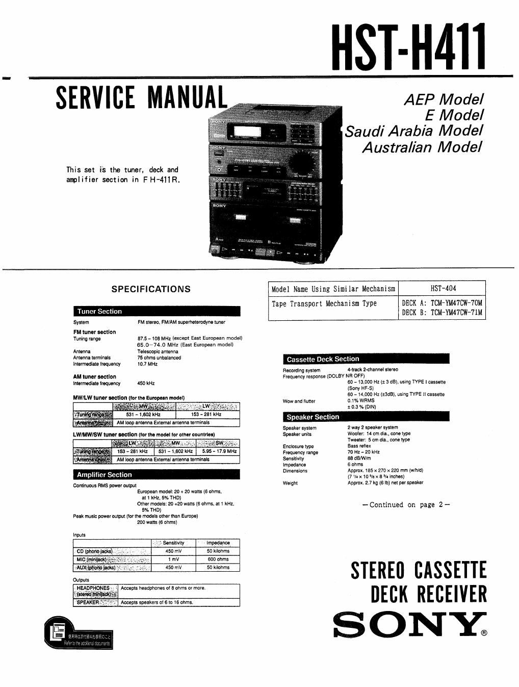
sony hsth 411 service manual

Extracted text from sony hsth 411 service manual (Ocr-read)


Page 2

HST-H41 1

Power requirements European Mei: 220 V AC. 50/60 H1
Model I01 other coumriesi
10 ~ 120 V or 220 - 240 V AC adjustablc,
50/50 Hz
Power consumption European melt $5 watts

Model in! other countries: 65 watts
Dimensions Approx. 595 x 270 x 250 mm (IN/hm)

(23v: x toy- x launches)

incl. prolecting parts and controls
Weight Approx. 9.5 kg (20 It: 15 oz) not
Suwlied accessories RM-S90 Hermie Commands! (1)

SONV SUM~3 (NS) batteries (2)

AM loop antenna (1)

Design and specifications subject to change without notice.
Not.

This appliance ccnlorms with EEC Directive swans/sec regarding lnlerlerom
suppression.

Tuner section

~ Consult the below chart tor the band stations
receivable for the model available in your

country.

Europeanmodel LW/MW/FM
Modeltorother LW/MWISWIFM
countries

- You can store up to 25 stations in the
memory

Amplifier sectlon

- DBFB (Dynamic Bass Feedback) system
oi the European models. or SAT (Super
Acoustic Turbo) system oi the model let
other countries reinlorces bass sound.

- 5-band stereo graphic equalizer adjusts
the sound quality to your prelerence during
playback.

Cassette deck section

- Double decks allow you to:
- dub tapes.
~ play back one deck then the other
successively.

- MODEL IDENTIFICATION -
(Specification Label)

SONY MODEL NO. HST-H411

STEREO CASSETTE DECK RECEIVER

TABLE OF CONTENTS

Section Eggg
SECTION 1 GENERAL 3
SECTION 2 DISASSEMBLY ~~~ ~~~~~~~ ~ ------ n~~ 6
SECTION 3 MECHANICAL ADJUSTMENT 6
SECTION 4 ELECTRICAL ADJUSTMENT -- 7

SECTION 5 DIAGRAMS

5~1. Semiconductor Lead Layouts "'n- 10
5-2. Circuit Boards Location ~~'~"'" 10
5-3. Printed Wiring Boards "'"'""-"' 11
5-4. Schematic diagram

- Deck AMP Section --~-'~-~'~- 15

1C Block diagrams ...........u........ 1'7
5-5. Schematic diagram

_. Tuner Section __ ............... 19
SECTION 6 EXPLODED VIEWS ~-~-~~~~~-~- 23
SECTION 7 ELECTRICAL PARTS LIST ~-~'~- 27

Dolby noise reduction manufactured under license Irom
Dolby Laboratories Licensing Corporation.
DOLBY" and the double-D symbol DD are trademarks of
Dolby Laboratories Licensing Corporation.

SAFETV-RELATED COMPONENT WARNINGII

COMPONENTS IDENTIFIED 8V MARK A OR DOTTED
LINE WITH MARK A ON THE SCHEMATIC DIAGRAMS
AND IN THE PARTS LIST ARE CRITICAL TO SAFE
OPERATION. REPLACE THESE COMPONENTS WITH
SONY PARTS WHOSE PART NUMBERS APPEAR AS
SHOWN IN THIS MANUAL OR IN SUPPLEMENTS PUB-
LISHED BY SONY.

4-942-512-01: E/ Australian model
4-942-612-11: Saudi Arabia model
4-942-613-01
4-942-613-11
4-942-614-01: East European model
4-942-615-01: Germany model
4-942-616-01: Italian model

} : AEP model