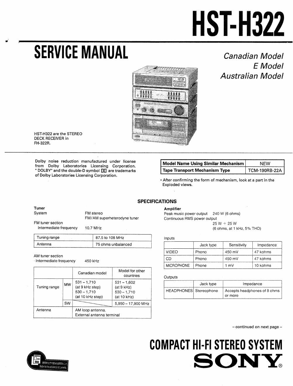
Sony hsth 322 service manual
This is the 41 pages manual for sony hsth 322 service manual.
Read or download the pdf for free. If you want to contribute, please upload pdfs to audioservicemanuals.wetransfer.com.
Extracted text from sony hsth 322 service manual (Ocr-read)
Page 2
HST-H322
Cassette deck TABLE OF CONTENTS
Recording system 4-track 2-channel Stereo
Frequency response With Type l cassette (Sony HF-S)
40 Hz to 13 kHz (:3 dB) w my; Bagg
Wow ant flutter 01 % (WRMS)
1. GENERAL
General
power requirements Canadian model Parts Identification .................................................... 4
120 V AC, 60 Hz
Australian model
240 v, 50 Hz 2. DISASSEMBLY 5
Model for other countries
110- 120/220-2140 V,
adjustable, 50/60 Hz
Power consumption Canadian model 105 w 3. MECHANICAL ADJUSTMENTS 5
Models for other countries 75 W
Weight Approx. 4.7 kg (10 lb 2 Oz)
Dimensions Approx 225 x 270 x 250 mm 4 ELECTRICAL ADJUSTMENTS 6
(87/; X 103/ X 10'/. inches)
(w/h/d. including projections)
5. DIAGRAMS
Design and specifications subject to change without notice. 5-1. Circuit Boards Location .................................. 9
5-2. Pin Functions Of ICSO1 ................................... 10
5-3. IC Block Diagrams ..... . .................................... 11
5-4. Semiconductor Lead Layouts ......................... 13
5-5. Printed Wiring Board
~ Tuner, PC Main section - .
5-6. Schematic Diagram
- Tuner, PC Main section - ............................. 17
57. Printed Wiring Board
- TC Main, Panel section - ..
5-8. Schematic Diagram
15
21
- TC Main, Panel section ....... . ............... 25
5-9. Printed Wiring Board
- Power, MD section - .................................... 29
5-10. Schematic Diagram
. Power, MD section - 33
6. EXPLODED VIEW
SAFETY~RELATED COMPONENT WARNINou
64. Front Panel Section 37
COMPONENTS IDENTIFIED BY MARK A OR DOTTED LINE A A
- . n ................ i ....................
WITH MARK A ON THE SCHEMATIC DIAGRAMS AND IN 62 Mechanism Sectio 1 38
THE PARTS LIST ARE CRITICAL To SAFE OPERATION. REPLACE 6-3. Mechanism Section 2 ..................................... 39
THESE COMPONENTS WITH SONY PARTS WHOSE PART 6-4. Mechanism Section3 ..................................... 40
NUMBERS APPEAR AS SHOWN IN THIS MANUAL OR IN
SUPPLEMENTS PUBLISHED BY SONY.
7 . ELECTRICAL PARTS LIST 41
ATTENTION AU COMPOSANT AVANT RAPPORT
A LA SECURITEI
LES COMPOSANTS IDENTIFIEs PAR UNE MAROUE A SUR
LEs DIAGRAMMES SCHEMATIQUES ET LA LISTE DES PIEcEs
SONT CRITIQUES POUR LA SECURITE DE FONCTIONNE~
MENT. NE REMPLAcER SES COMPOSANTS OUE PAR DES
PIECES SONY DONT LEs NUMERos SONT DONNEs DANS
CE MANUEL ou DANS LES SUPPLEMENTS PUBLIES PAR
SONY.