Sony hstd 307 service manual

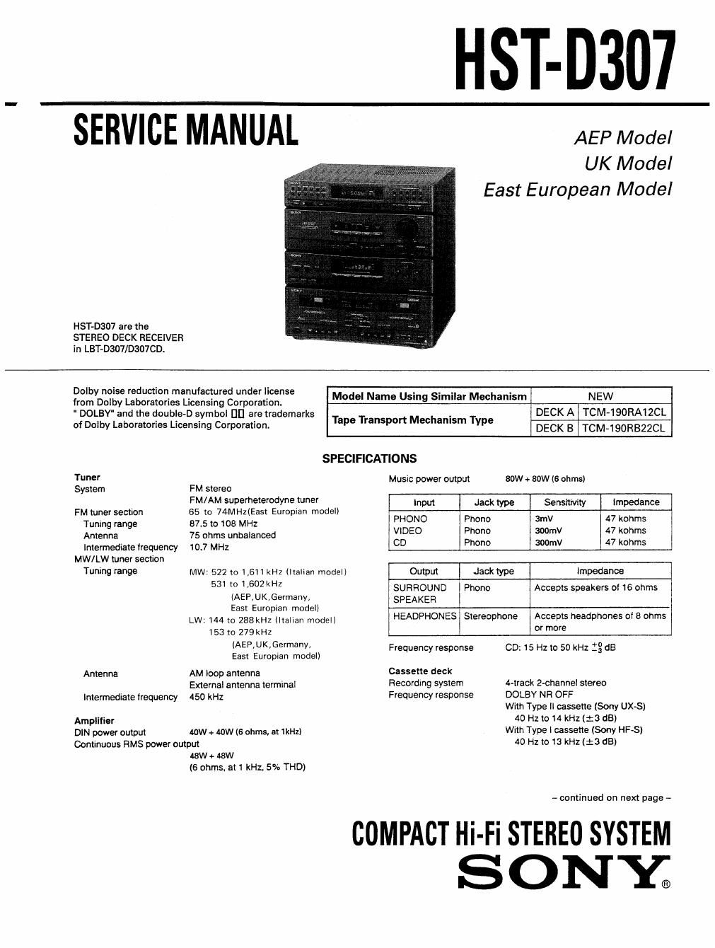
This is the 57 pages manual for sony hstd 307 service manual.
Read or download the pdf for free. If you want to contribute, please upload pdfs to audioservicemanuals.wetransfer.com.

Page: 1 / 57
sony hstd 307 service manual

Extracted text from sony hstd 307 service manual (Ocr-read)


Page 2

HST-D307

Turntable (Except lor HST model) TABLE OF CONTENTS

Platter 300m

Tone arm type Dynamically balanced

Cartridge type Moving magnet type . .

Stylus emu (0.6 mil diamond) 5-9-9119 LII-Q 539$
Weight Approx. 2.3kg

Dimensions Approx. 355 x 95 x 345 mm 1. GENERAL

(w/h/dl, including proiectionsl

1-1. Location of Controls .. 3
Supplied accessorlu
Remote commander RM-5305 (1) 2- ADJUSTMENTS
Batteries Sony SUM-3 (NS) (2) . t
M We mama (1) (excluding Germany mode" 2-1. Mechanical Adjustments ................................ 4
AM loop antenna (1) _ - -
45mm adapter (1) (finding for HST mode" 2 2. Electrical Adjustments .................................... 4
3. DIAGRAMS
General
Power requirements 220 - 230v AC, 50/6on 3-1 . Circuit Boards Location .................................. 1 0
240v Ac, 5on (UK model) .
Powerwnsummlon 130w 3-2. Block Diagrams .............................................. 11
250w (UK model) , -
Ac 0mm Switched 100w max. 3 3. 10 Block Diagrams ............... 13
Weight Approx. 9.1kg 3-4. Semiconductor Lead Layouts 13
D'"°""°" (mi: flit/3%,? """ a-s. Printed Wiring Boards (TC Section) ............... 16
(Wild. including projections) 34:). Schematic Diagram (TC Section) ................... 19
37. Printed Wiring Boards (Main Section) .. 24
3-8. Schematic Diagram (Main Section) 29
MODEL IDENTIFICATION 3-9. Printed Wiring Boards (Panel Section). .. 34
_ SPECIFICATION LABEL __ 3-10. Schematic Diagram (Panel Section) .............. 39
4. EXPLODED VIEWS
4-1 . Cabinet Section .............................................. 43
SON'Y; MODEL No. 31.43307 4-2. Front Panel Section ............. 44
4-3. Mechanism Deck Section 1 . 45
STEREO DECK RECE'VER +4. Mechanism Deck Section 2 ............................ 46
4-5. Mechanism Deck Section 3 ............................ 47
5. ELECTRICAL PARTS LIST ......... . ............ . ..... 48
SUPPLEMENT-1 (CIS Model)
SERIAL NO.
ASSEMBLED m MALAVSIA
SAFETY-RELATED COMPONENT WARNING
AEP. Germany. Italian, COMPONENTS IDENTIFIED av MARK A on DOTTED LiNE
East European MODEL : AC 220 -230V, 50/60Hz WITH MARK A ON THE SCHEMATIC DIAGRAMS AND IN
UK MODEL : AC240V, 5on THE PARTS LIST ARE CRITICAL TO SAFE OPERATION. REPLACE

THESE COMPONENTS WITH SONY PARTS WHOSE PART
NUMBERS APPEAR AS SHOWN IN THIS MANUAL OR IN
SUPPLEMENTS PUBLISHED BY SONY.