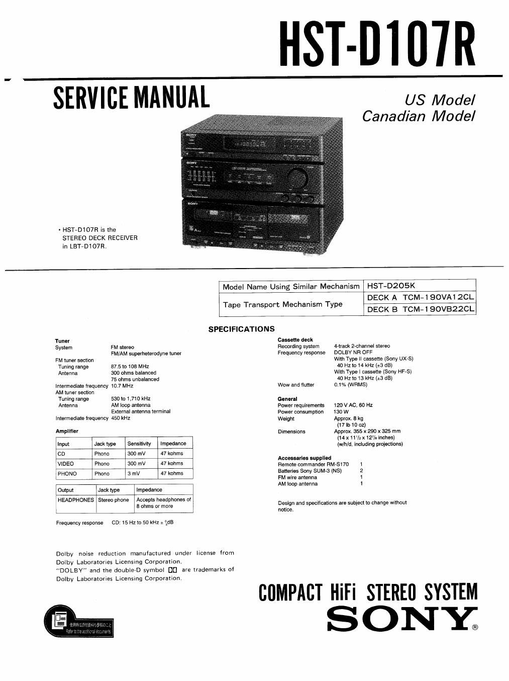
Sony hstd 107 r service manual
This is the 38 pages manual for sony hstd 107 r service manual.
Read or download the pdf for free. If you want to contribute, please upload pdfs to audioservicemanuals.wetransfer.com.
Extracted text from sony hstd 107 r service manual (Ocr-read)
Page 1
HST-Di 07R
SERVICE MANUAL us Model
Canadian Model
- HST-D107R is the
STEREO DECK RECEIVER
in LBT-D107Rt
Model Name Using Similar Mechanism HST-D205K
T T rt M h T DECK A TCM-l 90VA12CL
ape ranspo ec anlsm ype
DECK B TCM-i 90VBZZCL
SPECIFICAT|ONS
Tunvr cassette deck
System FM stereo Recording system rack 2-channel stereo
FM/AM superheterodyne tuner Frequency response DOLBY NR OFF
FM tuner section With Type ll cassette (Sony UX-S)
Tuning range 87.5 to 108 MHz 40 Hz to I4 kHz (:3 dB)
Antenna 300 ohms balanced With Type | cassette (Sony HFVS)
75 ohms unbalanced 40 Hz to 13 kHz (3.3 dB]
Intermediate lrequency 10,7 MHz Wow and flutter 0.1% (WFlMS)
AM tuner section
Tuning range 530 lo 1,710 kHz General
Antenna AM loop antenna Power requirements 120 V Ac, 60 Hz
External antenna terminal Power consumpfiofl 130 w
Intermediate frequency 450 kHz Weight Approx, 8 kg
(17 lb 10 oz)
AMPIIfler Dimensions Approx. 355 x 290 x 325 mm
., (14x 11'sz 12/. Inches)
Input Jack type Sensitrvrty Impedance (w/h/d. Including projections)
CD Phone 300 mV 47 kohms
Accessarles supplied
VIDEO Phono 300 mV 47 kohrns Remote wmmande, RM-SWD 1
FHONO Phone 3 "IV 47 kohrns Baha'i 50W SUM-3 (NS) 2
FM wire antenna 1
AM loop antenna 1
Output Jack type Impedance
HEADPHONES St h Acne ts h d h t
em p we a or; slim ° Daeign and specifications are subject to change without
n lee.
Frequency response CD: 15 Hz to 50 kHz : gdB
Dolby noise reduction manufactured under license from
Dolby Laboratories Licensing Corporation
"DOLBY" and the double-D symbol DU are trademarks of
Dolby Laboratories Licensing Corporation.
COMPACT HiFi STEREO SYSTEM
SONY;
Page 2
HST-D107R
SAFETY CHECK-OUT
After correcting the original service problem,
perform the following safety check before releasing
the set to the customer:
Check the antenna terminals, metal trim, metallized
knobs, screws, and all other exposed metal parts for
AC leakage. Check leakage as described below,
LEAKAGE TEST
The AC leakage from any exposed metal part to
earth ground and from all exposed metal parts to any
exposed metal part having a return to chassis, must
not exceed 05 mA (500 microampers) Leakage
current can be measured by any one of three
methods.
1. A commercial leakage tester, such as the
Simpson 229 or RCA WT-540Ai Follow the
manufacturers instructions to use these instru-
ments.
2. A battery-operated AC milliammeter. The Data
Precision 245 digital multimeter is suitable for
this job.
3. Measuring the voltage drop across a resistor by
means of a VOM or battery-operated AC volt-
meter. The limit indication is 0.75 V, so
analog meters must have an accurate low-
voltage scale, The Simpson 250 and Sanwa
SHA63Trd are examples of a passive VOM that
is suitable, Nearly all battery operated digital
multimeters that have a 2 V AC range are
suitable (See Fig. A)
To Exposed Metal
Parts on Sat
A0
0.15]: gum / voltmeter
(0.75v)
1.5 Earth Ground
Fig, A. Using an AC voltmeter to check AC leakage.
SAFETY-RELATED COMPONENT WARNING
COMPONENTS IDENTIFIED BY MARK A OR DOTTED
LINE WITH MARK A ON THE SCHEMATIC DIAGRAMS
AND IN THE PARTS LIST ARE CRITICAL TO SAFE
OPERATION. REPLACE THESE COMPONENTS WITH
SONY PARTS WHOSE PART NUMBERS APPEAR AS
SHOWN IN THIS MANUAL OR IN SUPPLEMENTS PUB-
LISHED BY SONY.
m
S ECT
S ECT
S ECT
TABLE OF CONTENTS
ION 1. GENERAL ~ 3
ION 2. ADJUSTMENTS ............................................. 4
ION 3. DIAGRAMS
3.1. Circuit Boards Location .................................... 7
3-2. Printed Wiring Boards - Audio Section - ------------ 8
3-3. Schematic Diagrams - Audio Section -
34. Printed Wiring Boards - Panel Section ~- ~~~~~~~~~~~~ 14
3-5. Schematic Diagrams - Panel Section - --------------- 17
3-6 Schematic Diagrams - TC Section - --------------- 2]
3-7. Printed Wiring Boards - TC Section -- »
3-& Schematic Diagrams -- Tuner Section - ~~~~~~~~~~~~~~~ 29
3-9, Semiconductor Lead Layouts ------------------------------ 33
SECTION 4. EXPLODED VIEWS
4.1, Cabinet Section ................................................ 34
4-2, Front Panel Section
4-3. Mechanism Deck Section (1) .............................. 35
44, Mechanism Deck Section (2) ------------------------------ 37
4-5, Mechanism Deck Section (3) .............................. 38
SECTION 5 ELECTRICAL PARTS LIST --------------------------------- 39
ATTENTION AU COMPOSANT AVANT RAPPORT
A LA SECURITE!
LES composmrs IDENTIFIES PAH UNE MAROUE A
suR LES DIAGRAMMES SCHEMATIQUES ET LA LISTE
DES PIECES SONT CRITIQUES POUR LA SECURITE
DE FONCTIONNEMENT. NE REMPLACER CES com-
POSANTS QUE PAR DES PIECES sowv DONT LES
NUMEROS som DONNES DANS CE MANUEL ou
DANS LES SUPPLEMENTS PUBLIES PAR souv.