Sony hcd xgr 99 av service manual

This is the 82 pages manual for sony hcd xgr 99 av service manual.
Read or download the pdf for free. If you want to contribute, please upload pdfs to audioservicemanuals.wetransfer.com.

Page: 1 / 82
sony hcd xgr 99 av service manual

Extracted text from sony hcd xgr 99 av service manual (Ocr-read)


Page 1

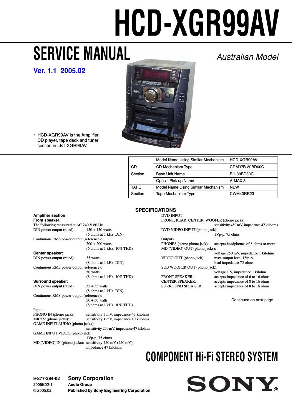
HOD

-XGR99AV

SERVICE MANUAL_

Ver. 1.1 2005.02

- HCD-XGR99AV is the Amplifier,
CD player, tape deck and tuner
section in LBT-XGR99AV.

Australian Model

Model Name Using Similar Mechanism HCD-XGRSOAV
CD CD Mechanism Type CDM37B-30BDGOC
Section Base Unit Name BU-3OBDGDC
Optical Pick-up Name A-MAX.3
TAPE Model Name Using Similar Mechanism NEW
Section Tape Mechanism Type CWM43FIF123

SPECIFICATIONS

Amplifier section
Front speaker:
The following measured at. AC 240 V 60 Hz
DIN power output (rated): 150 + 150 watts

(6 ohms at 1 kHz, DIN)
Continuous RMS power output (reference):

200 + 200 watts

(6 ohms at 1 kHz, 10% THD)
Center speaker:
DIN power output (rated): 35 watts
(8 ohms at 1 kHz, DIN)
Continuous RMS power output (reference):

50 watts

(8 ohms at 1 kHz, 10% THD)
Surround speaker:
DIN power output (rated): 35 + 35 watts
(8 ohms at 1 kHz, DIN)
Continuous RMS power output (reference):

50 + 50 watts

(8 ohms at 1 kHz, 10% THD)
Inputs
PHONO IN (phono jacks): sensitivity 3 mV, impedance 47 kiiohms
MICl/2 (phone jacks): sensitivity 1 mV, impedance IO kilohms
GAME INPUT AUDIO (phono jacks):

sensitivity 250 mV, impedance 47 kiiohms
GAME INPUT VIDEO (phono jack):

le-p, 75 ohms
MD (VIDEO) IN (phono jacks): sensitivity 450 mV (250 mV),

impedance 47 kilohms

DVD INPUT
FRONT, REAR, CENTER, WOOFER (phono jacks):
sensitivity 450 mV, impedance 47 kilohms
DVD VIDEO INPUT (phono jack):
1Vp-p, 75 ohms
Outputs
PHONES (stereo phone jack): accepts headphones of 8 ohms or more
MD (VIDEO) OUT (phono jacks):
voltage 250 mV, impedance 1 kilohms
max. output level le-p,
load impedance 75 ohms
SUB WOOFER OUT (phono jack):
voltage 1 V, impedance 1 kilohm

VIDEO OUT (phono jack):

FRONT SPEAKER: accepts impedance of 6 to 16 ohms
CENTER SPEAKER: accepts impedance of 8 to 16 ohms
SURROUND SPEAKER: accepts impedance of 8 to 16 ohms

- Continued on next page -

COMPONENT Hi-Fi STEREO SYSTEM

9-877-284-02 Sony Corporation
2005802-1 Audio Group
© 2005.02 Published by Sony Engineering Corporation

SONY;

Page 2

HCD-XGR99AV

CD player section
System
Laser

Frequency response
Signal-to-noise ratio
Dynamic range

CD OPTICAL DIGITAL OUT

Compact disc digital audio system
Semiconductor laser (A=795 nm)
Emission duration: continuous

2 1-11 - 20 kHz ($0.5 dB)

More than 90 dB

More than 90 dB

(square optical connectorjack, rear panel)

Wavelength
Output level

Tape deck section

Recording system
Frequency response

Tuner section

660 nm
-18 dBm

4-track 2-channel, stereo
50 - 13,000 Hz (:3 dB),
using Sony TYPE I cassettes

FM stereo, FM/AM superheterodyne tuner

FM tuner section
Tuning range:
Antenna

Antenna terminals
Intermediate frequency
AM tuner section
Tuning range:

Antenna
Antenna terminals
Intermediate frequency

General

Power requirements
Power consumption
Dimensions (w/h/d)
Mass

Supplied accessories:

87.5 - 108.0 MHz (50 kHz step)
FM lead antenna

75 ohms unbalanced

10.7 MHZ

530 - 1,710 kHz

(with the tuning interval set at 10 kHz)
531 - 1,602 kHz

(with the tuning interval set at 9 kHz)
AM loop antenna

External antenna terminal

450 kHz

230 - 240 V AC, 50/60 Hz
230 watts

Approx. 355 x 425 x 451 mm
Approx. 15.4 kg

AM loop antenna (1)
FM lead antenna (1)
Speaker cords (5)
Speaker pads (12)
Remote Commander ( 1)
Batteries (2)

Design and specifications are subject to change without notice.

Notes on chip component replacement

- Never reuse a disconnected chip component.

- Notice that the minus side of a tantalum capacitor may be
damaged by heat.

Flexible Circuit Board Repairing

- Keep the temperature of soldering iron around 270°C
during repairing.

- Do not touch the soldering iron on the same conductor of the
circuit board (within 3 times).

- Be careful not to apply force on the conductor when soldering
or unsoldering.

CAUTION

Use of controls or adjustments or performance of procedures
other than those specified herein may result in hazardous radiation
exposure.

CLASS 1 LASER PRODUCT
LUOKAN I LASERLAITE
KLASS 1 LASERAPPARAT

This appliance is classified as a CLASS 1 LASER product. The
CLASS 1 LASER PRODUCT MARKING is located on the rear
exterior.

CAUTION : lNVlSlELE LASER RADIATION WHEN OPEN AND
INTERLOCKS DEFEATED AVOID EXPOSURE TO BEAM
ADVARSEL : USVNLIG LASERSTRALING VED ABNING NAR
SIKKERHEDSAFERVDERE ER UDE AF FUNKTIDN uNoGA UDSAEITELSE
FOR STRALING

VORSICHT : UNSICHTBARE LASERSYRAHLUNG wENN
AEDECKUNG sEoEENEr mm SICHEREIYSVERRIEGELUNG
UBERERUCKT mew DEM STHAHL AUSSETZEN

VA R O I : Avm'mEssA m SUOMLUKITUS oHirErrAEssA OLET ALT
rum NAKVMATYOMALLE LASERSATEILVLLE. AtA KAYSO SAIEESEEN
VA R N I N G ' osttwc LASERSTRALING NAR DENNA DEL AR OPPNAD
OCH SPARREN AR URKOPPLAD EETRAKTA Ed swam

ADVERS E L : usttlo LASERSYRALING NAR DEKSEL APNES co
SIKKERHEDSLAS BRVTES UNNGA EKSPONERING an srRAtEN
VIGYAZATI : A BURKDLAT NYITASAKDR LAYHATAYLAN LEZERsu
GARVESZELVV KEKULJE A aEsuammsrr

SAFETY-RELATED COMPONENT WARNING I!

COMPONENTS IDENTIFIED BY MARK MR DOTTED LINEWITH
MARK AON THE SCHEMATIC DIAGRAMS AND IN THE PARTS
LIST ARE CRITICAL TO SAFE OPERATION. REPLACE THESE
COMPONENTS WITH SONY PARTS WHOSE PART NUMBERS
APPEAR AS SHOWN IN THIS MANUAL OR IN SUPPLEMENTS
PUBLISHED BY SONY.