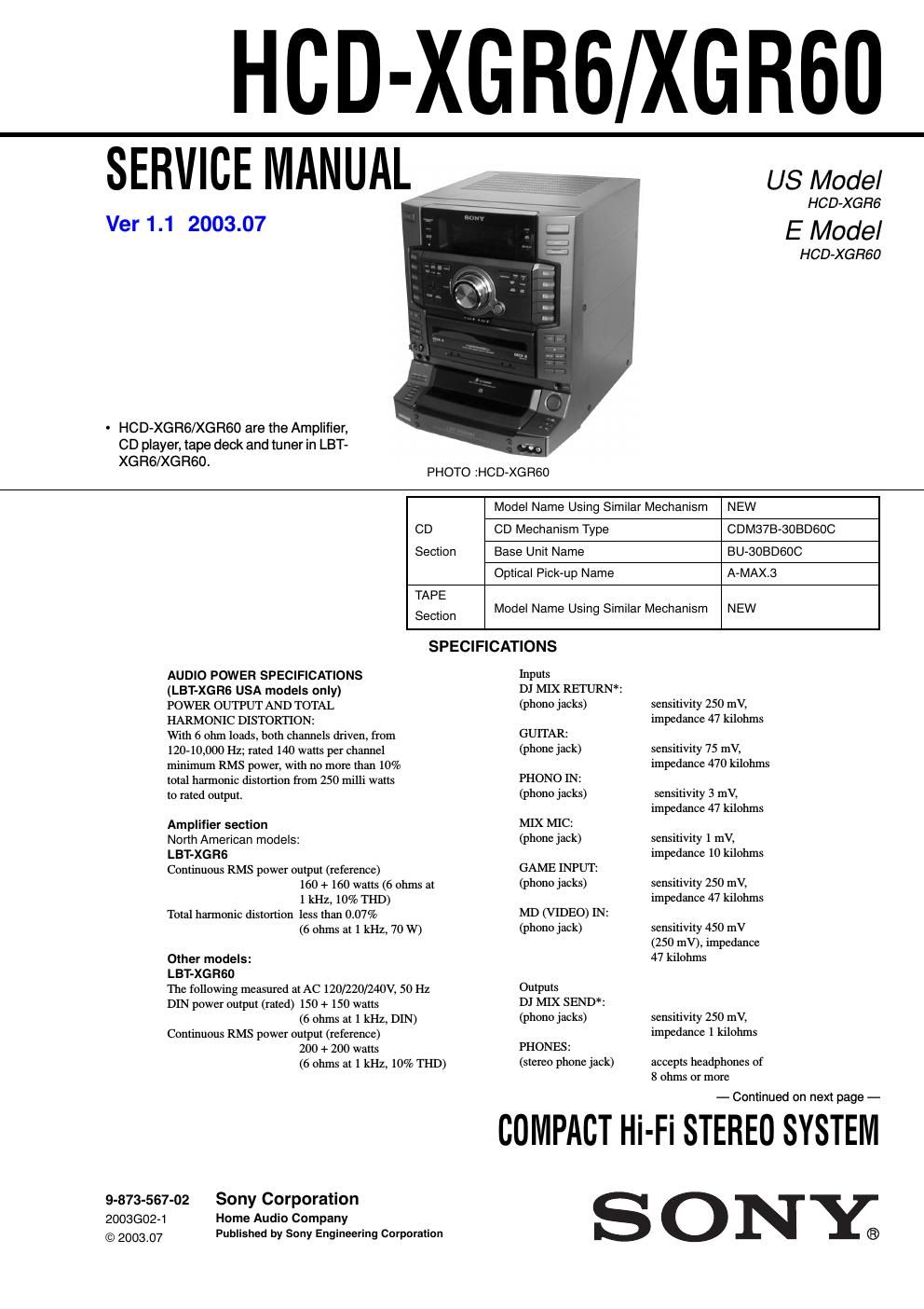
Sony hcd xgr 6 service manual
This is the 74 pages manual for sony hcd xgr 6 service manual.
Read or download the pdf for free. If you want to contribute, please upload pdfs to audioservicemanuals.wetransfer.com.
Extracted text from sony hcd xgr 6 service manual (Ocr-read)
Page 2
HCD-XGRG/XGRGO
MD (VIDEO) OUT:
(phono jacks) voltage 250 mV
impedance 1 kilohms
FRONT SPEAKER: accepts impedance of 6 to
16 ohms
* North American and Mexican models only
CD player section
System
Laser
Frequency response
Compact disc and digital
audio system
Semiconductor laser
(1:795 nm), Emission
duration: continuous
2 Hz - 20 kHz (i0.5 dB)
General
Power requirements
North American models:
Mexican model:
Other models:
Power consumption
U.S.A. models:
LBT-XGR6
Other models:
LBT-XGR60
Dimensions (w/h/d)
Mass :
LBT-XGR6
LBT-XGR60
120 V AC, 60 Hz
120 V AC, 60 Hz
120 V, 220 V or 230 -
240 V AC, 50/60 Hz
Adjustable with voltage
selector
240 watts
180 watts
Approx. 355 X 425 X 451 mm
Approx. 13.0 kg
Approx. 14.7 kg
Signal-to-noise ratio More than 90 dB
Dynamic range More than 90 dB
CD OPTICAL DIGITAL OUT
(Square optical connectorjack, rear panel)
Wavelength: 660 nm
Output level -18 dBm
Tape player section
Recording system
Frequency response
Tuner section
4-track 2-channel stereo
40 -13,000 Hz (i3 dB),
using Sony TYPE I cassette
FM stereo, FM/AM superheterodyne tuner
FM tuner section
Tuning range
North American models:
Other models:
Antenna
Antenna terminals
Intermediate frequency
AM tuner section
Tuning range
Pan- American models:
Other models:
Antenna
Antenna terminals
Intermediate frequency
87.5 - 108.0 MHz
(100 kHz step)
87.5 - 108.0 MHz
(50 kHz step)
FM lead antenna
75 ohms unbalanced
10.7 MHz
530- 1,710 kHz
(with the interval set at 10 kHz)
531 - 1,710 kHz
(with the interval set at 9 kHz)
531 - 1,602 kHz
(with the interval set at 9 kHz)
530- 1,710 kHz
(with the interval set at 10 kHz)
AM loop antenna
External antenna terminal
450 kHz
Supplied accessories: AM loop antenna (1)
FM lead antenna (1)
Speaker cords (2)
Speaker pads (8)
Remote commander (1)
Batteries (2)
Design and specifications are subject to change without notice.
Notes on chip component replacement
- Never reuse a disconnected chip component.
- Notice that the minus side of a tantalum capacitor may be
damaged by heat
Flexible Circuit Board Repairing
- Keep the temperature of soldering iron around 270°C
during repairing.
- Do not touch the soldering iron on the same conductor of the
circuit board (within 3 times).
- Be careful not to apply force on the conductor when soldering
or unsoldering.
CAUTION
Use of controls or adjustments or performance of procedures
other than those specified herein may result in hazardous radiation
exposure.
CLASS 1 LASER PRODUCT
LUOKAN 1 LASERLAITE
KLASS 1 LASERAPPARAT
This appliance is classified as a CLASS 1 LASER product. The
CLASS 1 LASER PRODUCT MARKING is located on the rear
exterior.
CAUTION . lNVlslBLE LASER RADWION WHEN OPEN AND
lNTERLocKs oars/rm: AVOlD Exposuwz m BEAM
ADVAFlSEL : USYNLlG LASERSTRAUNG on AEMNG NAR
SlKKERHEDSAFERVDERE ER qu AF FUNKTlON uNDoA UDSAEWELSE
Eon smAtwe
VORSICHT ' UNSlCHTBARE LASERSTRAHLUNG WENN
Aauzcxwe 520mm uNo SlCHERElTSVERRlEGELuNG
dBERBRUCKT mew DEM STRAHL AUSSEIZEN
VA R O : AvArtAEssA JA squAtuKlTusoHlYEWAEssA OLET ALF
mm NAKYMATYOMALLE tnsznsnamrs ALA KATSO sArEEsEEN
VA R N | N G : DSYNLlNG LASERSTRAUNG NAR DENNA DEL AR UPPNAD
OCH SPARREN AR momma EETRAKTA EJ STRALEN
ADVERS E l. . ustLlG LASERSYRAUNG NAR DEKSEL APNES co
SlKKERHEDSLAS arms: UNNGA EKSVDNERlNG ran swarm
VIGVAZATJ : A summon Nvmisnxoa LATHATATLAN LEZERSUV
GARVESZELY' KERULlE A BESUGARZASU