Sony hcd xb 500

This is the 88 pages manual for sony hcd xb 500.
Read or download the pdf for free. If you want to contribute, please upload pdfs to audioservicemanuals.wetransfer.com.

Page: 1 / 88
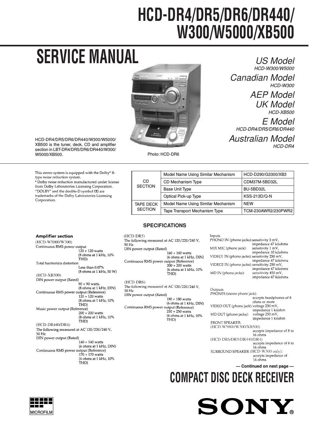
sony hcd xb 500

Extracted text from sony hcd xb 500 (Ocr-read)


Page 1

– 2 –

Page 2

– 3 – CAUTIONUse of controls or adjustments or performance of procedures other than those specif ied herein may result in hazardous ra- diation e xposure. Notes on c hip component replacement - Nev er reuse a disconnected c hip component. - Notice that the minus side of a tantalum capacitor may be damaged by heat. Fle xible Cir cuit Boar d Repairing - Keep the temperatur e of soldering iron around 270˚C during repairing. - Do not touch the soldering iron on the same conductor of the circuit board (within 3 times). - Be careful not to apply force on the conductor when soldering or unsoldering. SAFETY-RELA TED COMPONENT WARNING !! COMPONENTS IDENTIFIED BY MARK ! OR DO TTED LINE WITH MARK ! ON THE SCHEMA TIC DIAGRAMS AND IN THE P ARTS LIST ARE CRITICAL TO SAFE OPERA TION. REPLA CE THESE COMPONENTS WITH SONY PARTS WHOSE P ART NUMBERS APPEAR AS SHO WN IN THIS MANU AL OR IN SUPPLEMENTS PUBLISHED BY SONY .A TTENTION A U COMPOSANT A YANT RAPPOR T À LA SÉCURITÉ!! LES COMPOSANTS IDENTIFIÉS P AR UNE MARQUE ! SUR LES DIA GRAMMES SCHÉMA TIQUES ET LA LISTE DES PIÈCES SONT CRITIQ UES POUR LA SÉCURITÉ DE FONCTIONNEMENT . NE REMPLA CER CES COMPOSANTS Q UE P AR DES PIÈCES SONY DONT LES NUMÉR OS SONT DONNÉS D ANS CE MANUEL OU D ANS LES SUPPLÉMENTS PUBLIÉS P AR SONY. Laser component in this product is capable of emitting radiation exceeding the limit f or Class 1. This appliance is classif ied as a CLASS 1 LASER product.T he CLASS 1 LASER PR OD- UCT MARKING is located onthe r ear e xterior. This cautionlabel is locatedinside the unit. SAFETY CHECK-OUT After cor recting the original service problem, perfor m the follow- ing safety checks before releasing the set to the customer: Check the antenna ter minals, metal trim, metallized knobs, screws, and all other e xposed metal par ts for AC leakag e. Check leaka ge as descr ibed belo w. LEAKA GE The AC leakag e fr om an y exposed metal part to earth Gr ound and from all e xposed metal parts to any e xposed metal part having a r eturn to c hassis, must not exceed 0.5 mA (500 micr oampers). Leak- a g e current can be measured by an y one of three methods. 1. A commercial leaka ge tester , such as the Simpson 229 or RCA WT -540A. F ollow the manuf acturers instructions to use these instruments. 2. A ba ttery-opera ted AC milliammeter . The Data Precision 245 digital multimeter is suitab le for this job. 3. Measuring the v oltage drop across a r esistor by means of a VOM or battery-oper ated AC v oltmeter . The limit indication is 0.75 V , so analog meters must ha ve an accur ate low-voltage scale . The Simpson 250 and Sanw a SH-63Trd are examples of a pas- si ve V OM that is suita ble. Nearly all battery operated digital multimeters tha t have a 2V AC range are suitab le. (See Fig. A) Fig. A. Using an A C v oltmeter to c heck AC leakage . 0.15 µF To Exposed Metal Parts on Set 1.5k ACvoltmeter(0.75V) Earth Ground