Sony hcd w 55
This is the 41 pages manual for sony hcd w 55.
Read or download the pdf for free. If you want to contribute, please upload pdfs to audioservicemanuals.wetransfer.com.
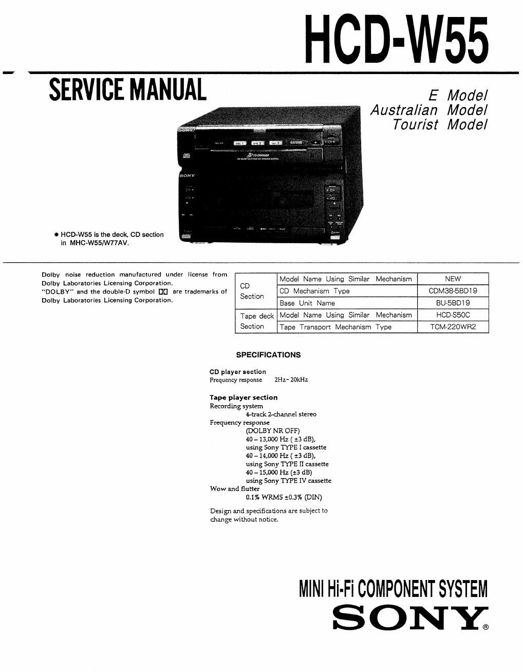
Extracted text from sony hcd w 55 (Ocr-read)
Page 1
HCD-W55
* SERVICE MANUAL
0 HCD-W55 is the deck, CD section
in MHC-W551W77AVl
E Model
Austral/an Model
Tourist Model
Dolby noise reduction manufactured under license from
Dolby Laboratories Licensing Corporarion.
"DOLBY" and the double-D symbol D0 are trademarks of
Dolby Laboratories Licensing Corporalion.
CD player section
Frequency response
Tape player section
Recording syslem
4-hck Z-channel stereo
Frequency response
(DOLBY NR OFF)
40 - 13,000 Hz ( :3 dB),
using Sony TYPE I mssette
40 -14,000 Hz ( :3 dB),
using Sony TYPE II cassette
40 -15,000 Hz (:3 dB)
using Sony TYPE IV cassette
Wow and flutter
0.1% WRMS 10.3% (DIN)
Design and specifications are subject to
change wi [bout notice.
CD Model Name Using Similar Mechanism NEW
, CD Mechanism Type CDM38-SBDIQ
Section
Base Unit Name BU-BBDIQ
Tape deck Model Name Using Similar Mechanism HOD-$500
Section Tape Transport Mechanism Type TCM-220WR2
SPECIFICATIONS
2Hz- ZOkHz
MINI Hi-Fi COMPONENT SYSTEM
SONE
Page 2
TABLE OF CONTENTS
Section Title Page Section Title Page
Specifications ............................................................... 1 6. EXPLODED VIEWS
6-1. Chassis Section ~~~~~~~~~
1. GENERAL ............................................................. 3 6.2. Front Panel Section
6-3. TC Mechanism Section-l ~~
2. DISASSEMBLY (TCM-ZZOWRZ)
2-1. Front Panel Section Removal~~~ 6-4 TC Mechanism Section-2 ~~~~~~~~~~~~~~~~~~~~~~~~~~~~~~~ 41
2-2. CD Block Removal ~~~~~~~~~~~~ (TCM-ZZOWRZ)
2-3. Cassette LID (A)/(B) Assy, 6-5. CD Mechanism Section (CDM38-5BD19) ~
Mechanism Deck Removal .................................. 5 6-6. Chassis Section (CDM38-SBD19)
67. Base Unit Section (BU-SBDI9) ~~
3. ADJUSTMENTS
3-1. Mechanical Adjustments ~- 7. ELECTRICAL PARTS LIST ~~~~~~~~~~~~~~~~~~~~~~~~~~~~~~~ 45
3-2. Electrical Adjustments -----
4. EXPLANATION OF IO TERMINALS ~~~~~~~~~~~~~~~~~~~~~~~ ll
5. DIAGRAMS
. Block Diagram ~~~~~~~~~~
. Circuit Boards Location
. Printed Wiring Boards - Main Section
. Schematic Diagram - Main Section -
Schematic Diagram - TC Section -
Printed Wiring Boards - TC Section
Schematic Diagram - CD Section - '
Primed Wiring Boards - CD Section
IC Block Diagrams .......................
mmmleI-v-v-vuuu
\ocaxlcnmasz--
SAFETY-RELATED COMPONENT WARNING
COMPONENTS IDENTIFIED BY MARK A OR DOTTED
LINE WITH MARK A ON THE SOHEMATIC DIAGRAMS
AND IN THE PARTS LIST ARE CRITICAL TO SAFE
OPERATION. REPLACE THESE COMPONENTS WITH
SONY PARTS WHOSE PART NUMBERS APPEAR AS
SHOWN IN THIS MANUAL OR IN SUPPLEMENTS PUE-
LISHED BY SONY.
SERVICING NOTE
0 Supplylng power during servlclng
This equipment cannot operate without using a separate power supply. Connect to the ST R-WSS when performing service work.
To apply power set the SYSTEM POWER switch on the Tuner/Amp to ON.
When other units are not available use the PFI-l power supply jig.
When using the PFJ-l, simultaneously press the- button and the-button to turn on the power.
[Connectlon Diagram]
PAM
(Power Supply Jlg)
--o/o-
POWEI? st
Se!
FIVE, 885, 737
MHC-6600, 5600:
3600, 2500
GDP/TC
Connector cable 17F
(supplied with seq
?
CNISI IIP
SYSTEM CONTROL 1
__2_