Sony hcd vx 550
This is the 82 pages manual for sony hcd vx 550.
Read or download the pdf for free. If you want to contribute, please upload pdfs to audioservicemanuals.wetransfer.com.
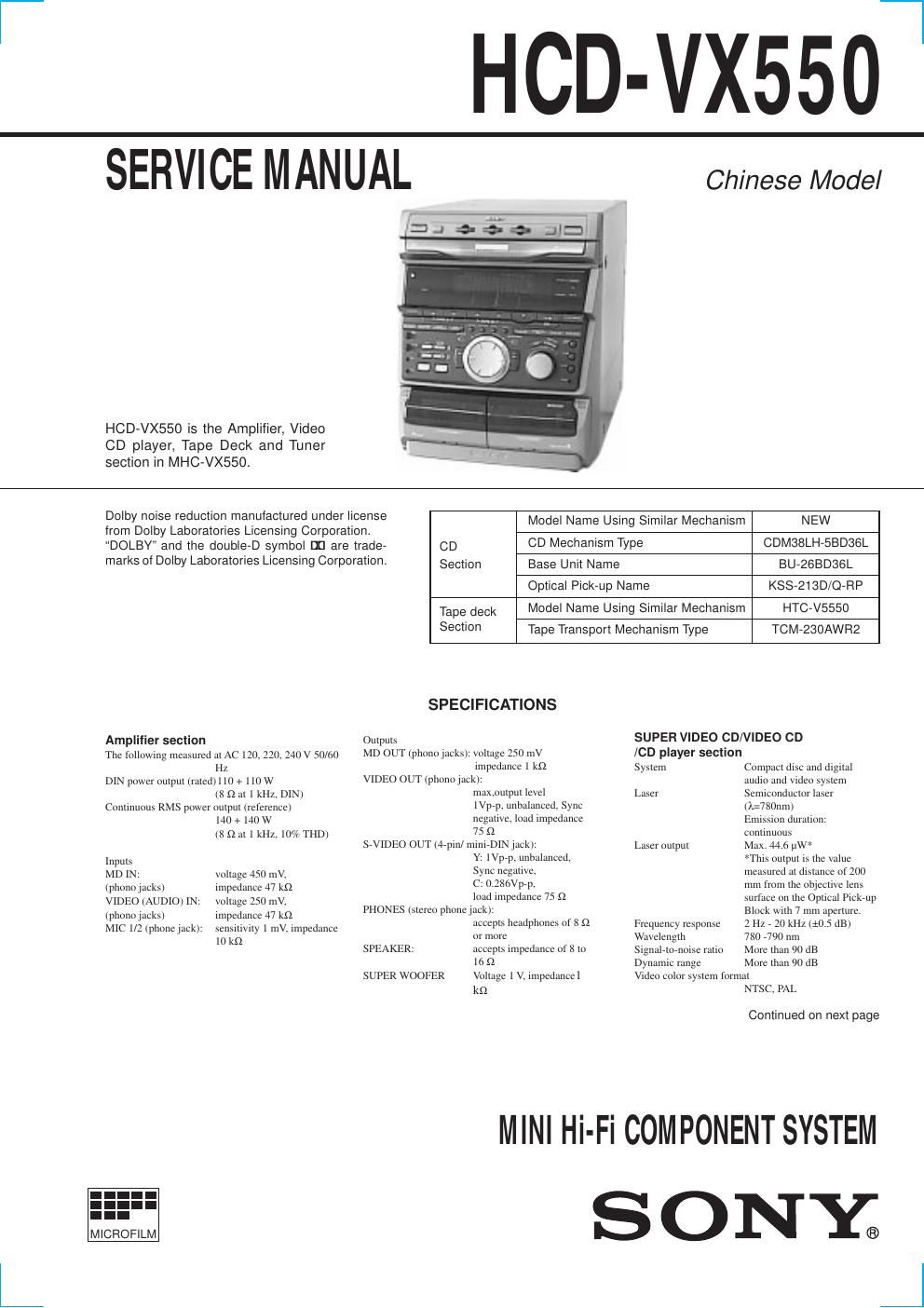
Extracted text from sony hcd vx 550 (Ocr-read)
Page 1
2 CD OPTICAL DIGITAL OUT (Square optical connector jack, rear panel) Wavelength 660 nm Output Level Ð18 dBm Tape player sectionRecording system 4-track 2-channel stereo Frequency response 40 - 13,000 Hz (±3 dB), (DOLBY NR OFF) using Sony TYPE I cassette 40-14,000 Hz (± 3 dB), using Sony TYPE II cassette Tuner sectionFm stereo, FM/ AM superheterodyne tuner FM tuner sectionTuning range 87.5-108.0 MHz Antenna FM lead antenna Antenna terminals 75 W unbalanced Intermediate frequency 10.7 MHz AM tuner sectionTuning range 2 Band type: 531-1,602 kHz (with the interval set at 9 kHz) 530-1,710 kHz (with the interval set at 10 kHz) 3 Band type: MW: 531-1,602 kHz (with the interval set at 9 kHz) 530-1,710 kHz (with the interval set at 10 kHz) SW: 5.95-17.90 MHz (with the interval set at 5 kHz) Antenna AM loop antenna Antenna terminals External antenna terminal Intermediate frequency 450 kHz GeneralPower requirements 220 V AC, 50/ 60 Hz Power consumption: 160 W Dimensions (w/h/d) Approx. 280 ´ 340 ´ 395 mm Mass: Approx. 10.0 kg Design and specifications are subject to change without notice. TABLE OF CONTENTS 1. SERVICING NOTESááááááááááááááááááááááááááááááááááááááááááááááááá 3 2. GENERAL .......................................................................... 5 3. DISASSEMBLY ................................................................ 8 4. TEST MODE ................................................................... 11 5. MECHANICAL ADJUSTMENTS ............................ 14 6. ELECTRICAL ADJUSTMENTS DECK Section .................................................................. 14 CD Section ....................................................................... 17 VIDEO Section ................................................................. 17 7. DIAGRAMS 7-1. Block Diagram CD SERVO Section .......................................................... 18 AUDIO/VIDEO CD Section ............................................ 19 TAPE DECK Section ....................................................... 20 MAIN Section .................................................................. 21 DISPLAY/KEY CONTROL/ POWER SUPPLY Section áááááááááááááááááááááááááááááááááááááááááááááááá 22 7-2. Circuit Board Location ááááááááááááááááááááááááááááááááááááááááááááááááááá\ áá 23 7-3. Printed Wiring Board BD Board .................................... 24 7-4. Schematic Diagram BD Board ....................................... 25 7-5. Schematic Diagram VIDEO Board (1/2) ........................ 26 7-6. Schematic Diagram VIDEO Board (2/2) ........................ 27 7-7. Printed Wiring Board VIDEO Board .............................. 28 7-8. Printed Wiring Boards CD MOTOR Section ................. 30 7-9. Schematic Diagram CD MOTOR Section ...................... 31 7-10. Printed Wiring Board AUDIO Board ............................. 32 7-11. Schematic Diagram AUDIO Board ................................ 33 7-12. Printed Wiring Board LEAF SW Board ......................... 34 7-13. Schematic Diagram LEAF SW Board ............................ 34 7-14. Printed Wiring Board MAIN Board ............................... 35 7-15. Schematic Diagram MAIN Board (1/4) ......................... 36 7-16. Schematic Diagram MAIN Board (2/4) ......................... 37 7-17. Schematic Diagram MAIN Board (3/4) ......................... 38 7-18. Schematic Diagram MAIN Board (4/4) ......................... 39 7-19. Printed Wiring Board PANEL Board ............................. 40 7-20. Schematic Diagram PANEL Board ................................ 41 7-21. Printed Wiring Board CD SW/5V POWER Board ........ 42 7-22. Schematic Diagram CD SW/5V POWER Board ........... 42 7-23. Printed Wiring Board TRANSFORMER Board ............ 43 7-24. Schematic Diagram TRANSFORMER Board ............... 43 7-25. Printed Wiring Board SURROUND Board .................... 44 7-26. Schematic Diagram SURROUND Board ....................... 44 7-27. IC Block Diagrams ........................................................... 45 7-28. IC Pin Function Description ............................................. 49 8. EXPLODED VIEWS ..................................................... 60 9. ELECTRICAL PARTS LIST ..................................... 68