Sony hcd s 20

This is the 40 pages manual for sony hcd s 20.
Read or download the pdf for free. If you want to contribute, please upload pdfs to audioservicemanuals.wetransfer.com.

Page: 1 / 40
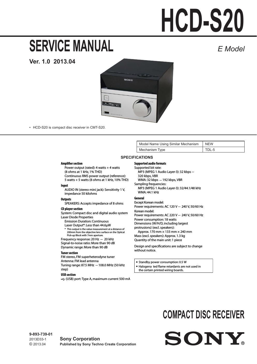
sony hcd s 20

Extracted text from sony hcd s 20 (Ocr-read)


Page 1

HOD-$20

SERVICE MANUAL

Ver. 1.0 2013.04

' HOD-820 is compact disc receiver in GMT-820.

E Model

NEW
TDL-5

Model Name Using Similar Mechanism

Mechanism Type

SPECIFICATIONS

Amplifiersection
Power output (rated): 4 watts + 4 watts
(8 ohms at 1 kHz, 1% THD)
Continuous RMS power output (reference):
5 watts + 5 watts (8 ohms at 1 kHz, 10% THD)

Input
AUDIO IN (stereo mini jack):Sensitivity I V,
impedance 50 kilohms

Outputs
SPEAKERS: Accepts impedance of8 ohms

(D player section
System: Compact disc and digital audio system
Laser Diode Properties

Emission Duration: Continuous

Laser Output*: Less than 44l6pW

* This output rs the value measurement at a distance of

200mm from the objective lens surface on the Optical
Pickup Black with 7mm aperture.

Frequency response: 20 Hz - 20 kHz
Signal-to-noise ratio: More than 90 dB

Dynamic range: More than 90 dB

Tuner section

FM stereo, FM superheterodyne tuner

Antenna: FM lead antenna

Tuning range: 87.5 MHz 7108.0 MHZ (50 kHz
step)

USB section

.6. (USB) port: Type A, maximum current 500 mA

9-893-739-01
20130334 Sony Corporation
© 2013.04 Published by Sony Techno Create Corporation

Supported audio formats
Supported bit rate:
MP3 (MPEG 1 Audio Layer-3): 32 kbps 7
320 kbps,VBR
WMA: 32 kbps 7192 kbps,VBR
Sampling frequencies:
MP3 (MPEG 1 Audio Layer-3):32/44.1/48 kHz
WMA:44.1 kHZ

General
Except Korean model:
Power requirements: AC 120 V - 240 V, 50/60 Hz
Korean model:
Power requirements: AC 220 V 7 240 V, 50/60 Hz
Power consumption: 18 watts
Dimensions (W/H/D, including largest
protrusions) (excl. speakers):
Approx. 170 mm x 133 mm x 240 mm
Mass (excl. speakers):Approx. 1.3 kg
Quantity of the main unit: I piece

Design and specifications are subject to change
without notice

0 Standby power consumption: 0.5 W

' Halogena ted flame retardants are not used in
the certain printed wiring boards.

COMPACT DISC RECEIVER

SONY;

Page 2

HCD-SZO

License and Trademark Notice TABLE OF CONTENTS

'MPEG Layere3 audio coding technology and
patents licensed from Fraunhofer IIS and 1- SERVICING NOTES -- 3
Thomson.

Windows Media is either a registered 2. DISASSEMBLY
trademark or trademark of Microsoft 2_1_ Disassembly Flow... 7
Corporation in the United States and/or other 21 Top Cover Assy 520 7
Fmr'es- _ _ _ 2-3. Power Cord (AC1), Rear Panel 8

'This product [5 protected by certain intellectual 24 CD Door (320) 8
property rights of Microsoft Corporation. Use 2_5' Loader (TDL-5)i§LOPUA (CDMI) 9
or distribution of such technology outside of ' y

26. Front Panel Block .............................. 9

this product is prohibited without a license

from Microsoft or an authorized Microsoft 27- VFD Board
subsidiaw. 2»8. USB Board
'All other trademarks and registered 2-9- MAIN Board. 11
trademarks are oftheir respective holders. In 210. POWER Board ................................................................ 11
this manual, W and ® marks are not specified.
3. TEST MODE ............................................................ 12
4. ELECTRICAL CHECK ......................................... 13
5. TROUBLESHOOTING .......................................... 14

6. DIAGRAMS

6-1. Block Diagram ...........
6-2. Board Component Diagram (1/3)
63. Board Component Diagram (2/3)
64. Board Component Diagram (3/3) ..
6-5. Printed Wiring Board - MAIN Board
6-6. Schematic Diagram - MAIN Board (1/6)
63/. Schematic Diagram » MAIN Board (2/6)
68. Schematic Diagram - MAIN Board (3/6) -..
6-9. Schematic Diagram - MAIN Board (4/6) -..
6-10. Schematic Diagram - MAIN Board (5/6) -..
6»11. Schematic Diagram » MAIN Board (6/6) -
642. Printed Wiring Board » USB Board
6-13. Schematic Diagram - USB Board
6-14. Printed Wiring Board - VFD Board
645. Schematic Diagram » VFD Board -
616. Printed Wiring Board - KEY Board
6-17. Schematic Diagram - KEY Board -
6-18. Schematic Diagram - POWER Board -
649. Printed Wiring Board » POWER Board


7. EXPLODED VIEWS
7»l. Top Cover Section...

This appliance is 7-2. Cha is Section
cuss LASER Paooucr classified 35 a CLASS 73. Front Panel Section.
tuwmrrssmmz 1 LASER product. This

KMSS 1 LASERAPPARAT

marking is located on
the rear exterior.

NOTES ON CHIP COMPONENT REPLACEMENT

- Never reuse a disconnected chip component.

- Notice that the minus side ofa tantalum capacitor may be dam»
aged by heat.

CAUTION

Use of controls or adjustments or performance of procedures
other than those specified herein may result in hazardous radia-
tion exposure.

SAFETY-RELATED COMPONENT WARNING!

COMPONENTS IDENTIFIED BY MARK A OR DOTTED LINE
WITH MARK A ON THE SCHEMATIC DIAGRAMS AND IN
THE PARTS LIST ARE CRITICAL TO SAFE OPERATION.
REPLACE THESE COMPONENTS WITH SONY PARTS
WHOSE PART NUMBERS APPEAR AS SHOWN IN THIS
MANUAL OR IN SUPPLEMENTS PUBLISHED BY SONY.

2