Sony hcd hp 7 service manual

This is the 66 pages manual for sony hcd hp 7 service manual.
Read or download the pdf for free. If you want to contribute, please upload pdfs to audioservicemanuals.wetransfer.com.

Page: 1 / 66
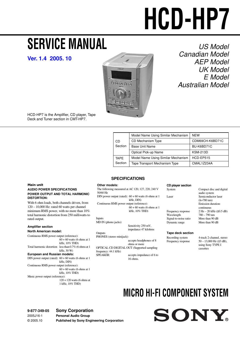
sony hcd hp 7 service manual

Extracted text from sony hcd hp 7 service manual (Ocr-read)


Page 1

2 HCD-HP7 SAFETY-RELATED COMPONENT WARNING!! COMPONENTS IDENTIFIED BY MARK 0 OR DOTTED LINE WITH MARK 0 ON THE SCHEMATIC DIAGRAMS AND IN THE PARTS LIST ARE CRITICAL TO SAFE OPERATION. REPLACE THESE COMPONENTS WITH SONY PARTS WHOSE PART NUMBERS APPEAR AS SHOWN IN THIS MANUAL OR IN SUPPLEMENTS PUBLISHED BY SONY.ATTENTION AU COMPOSANT AYANT RAPPORT À LA SÉCURITÉ! LES COMPOSANTS IDENTIFÉS PAR UNE MARQUE 0 SUR LES DIAGRAMMES SCHÉMATIQUES ET LA LISTE DES PIÈCES SONT CRITIQUES POUR LA SÉCURITÉ DE FONCTIONNEMENT. NE REMPLACER CES COMPOSANTS QUE PAR DES PIÈSES SONY DONT LES NUMÉROS SONT DONNÉS DANS CE MANUEL OU DANS LES SUPPÉMENTS PUBLIÉS PAR SONY. General Power requirements North American model: 120 V AC, 60 Hz European and Russian models: 230 V AC, 50/60 Hz Australian model: 230 – 240 V AC, 50/60 Hz Mexican model:120 V AC, 60 Hz Other models: 120 V, 220 V or 230 – 240 V AC, 50/60 Hz Adjustable with voltage selector Power consumption European and Russian models: 100 watts 0.35 watts (at the Power Saving Mode) Other models: 100 watts Dimensions (w/h/d) Approx. 199 252 400 mm Mass Approx. 7.0 kg Supplied accessories: Remote Commander (1) Batteries (2) AM loop antenna (1) FM lead antenna (1) Speaker pads (8) Design and specifications are subject to change without notice. Tuner section FM stereo, FM/AM superheterodyne tuner FM tuner section Tuning range Russian model: 65.0 – 74.0 MHz (There is no stereo effect) 87.5 – 108.0 MHz Other models: 87.5 – 108.0 MHz Antenna FM lead antenna Antenna terminals 75 ohms unbalanced Intermediate frequency 10.7 MHz AM tuner section Tuning range Pan-American model: 530 – 1,710 kHz (with the tuning interval set at 10 kHz) 531 – 1,710 kHz (with the tuning interval set at 9 kHz) European, Russian, Middle Eastern models: 531 – 1,602 kHz (with the tuning interval set at 9 kHz) Other models: 530 – 1,710 kHz (with the tuning interval set at 10 kHz) 531 – 1,602 kHz (with the tuning interval set at 9 kHz) Antenna AM loop antenna Antenna terminals External antenna terminal Intermediate frequency450 kHz

Page 2

3 HCD-HP7 1. SERVICING NOTES ······················································· 4 2. GENERAL ·········································································· 6 3. DISASSEMBLY 3-1. Case (Side-L)(Side-R), Tape Mechanism Deck (CMAL1Z234A) ······················ 9 3-2. Front Panel Section ······················································· 9 3-3. Panel Board ································································· 10 3-4. Back Panel Section ······················································ 10 3-5. MAIN Board ······························································· 11 3-6. PWR AMP Board, Power Transformer ······················· 11 3-7. CD Mechanism Deck (CDM69CH-K6BD71C) ·········· 12 3-8. Base Unit Section ························································ 12 3-9. Base Unit (BU-K6BD71C) ········································· 13 3-10. BD Board ····································································· 13 3-12. SW Board, Bracket (Top) Assy ··································· 14 3-13. CONNECTOR Board ·················································· 15 3-14. Motor (Stocker) Assy (Stocker)(M761) ······················ 15 3-15. Motor (Roller) Assy (Roller)(M781) ··························· 16 3-16. Motor (Mode) Assy (Mode)(M771) ···························· 16 3-17. Rubber Roller (Slider) Assy ········································ 17 3-18. Timing Belt (Front/Rear) ············································· 17 3-19. Cam (Gear) ·································································· 18 3-20. SENSOR Board ··························································· 18 4. ASSEMBLY 4-1. How to Install the Cam (Eject Lock) ···························· 18 4-2. How to Install the Cam (GEAR) ··································· 18 4-3. How to Install the Gear (MODE C) ······························ 19 4-4. How to Install the Gear (MODE CAM) ······················· 19 4-5. How to Install the Rotary Encoder (S702), Gear (STOCKER COMMUNICATION) ····················· 20 4-6. How to Install the Stocker Assy ···································· 20 5. TEST MODE ···································································· 22 6. MECHANICAL ADJUSTMENTS ····························· 23 7. ELECTRICAL ADJUSTMENTS ······························· 24 8. DIAGRAMS ······································································ 26 8-1. Block Diagram ···························································· 28 8-2. Printed Wiring Boards - BD Board - ······················ 29 8-3. Schematic Diagram - BD Board - ·························· 30 8-4. Printed Wiring Boards - Changer Section - ··········· 31 8-5. Schematic Diagram - Changer Section - ················ 32 8-6. Printed Wiring Boards - Main Section - ················· 33 8-7. Schematic Diagram - Main Section - ····················· 34 8-8. Printed Wiring Boards - Front Section - ················ 35 8-9. Schematic Diagram - Front Section - ····················· 36 8-10. Printed Wiring Boards - PWR AMP/Power Section - ································· 37 8-11. Schematic Diagram - PWR AMP/Power Section - ································· 38 8-12. IC Block Diagrams ······················································ 39 8-13. IC Pin Function Description ······································· 42 9. EXPLODED VIEWS 9-1. Case, Top Panel Section ·············································· 44 9-2. Front Panel Section ····················································· 45 9-3. Chassis Section-1 ························································ 46 9-4. Chassis Section-2 ························································ 47 9-5. CD Mechanism Section-1 (CDM69CH-K6BD71C) ··· 48 9-6. CD Mechanism Section-2 (CDM69CH-K6BD71C) ··· 49 9-7. CD Mechanism Section-3 (CDM69CH-K6BD71C) ··· 50 9-8. CD Mechanism Section-4 (CDM69CH-K6BD71C) ··· 51 9-9. CD Mechanism Section-5 (CDM69CH-K6BD71C) ··· 52 9-10. CD Mechanism Section-6 (CDM69CH-K6BD71C) ··· 53 9-11. Optical Pick-up Section (KSM-213D) ························ 54 10.ELECTRICAL PARTS LIST ······································· 55 TABLE OF CONTENTSVer 1.1 2003.11