Sony hcd h 61
This is the 101 pages manual for sony hcd h 61.
Read or download the pdf for free. If you want to contribute, please upload pdfs to audioservicemanuals.wetransfer.com.
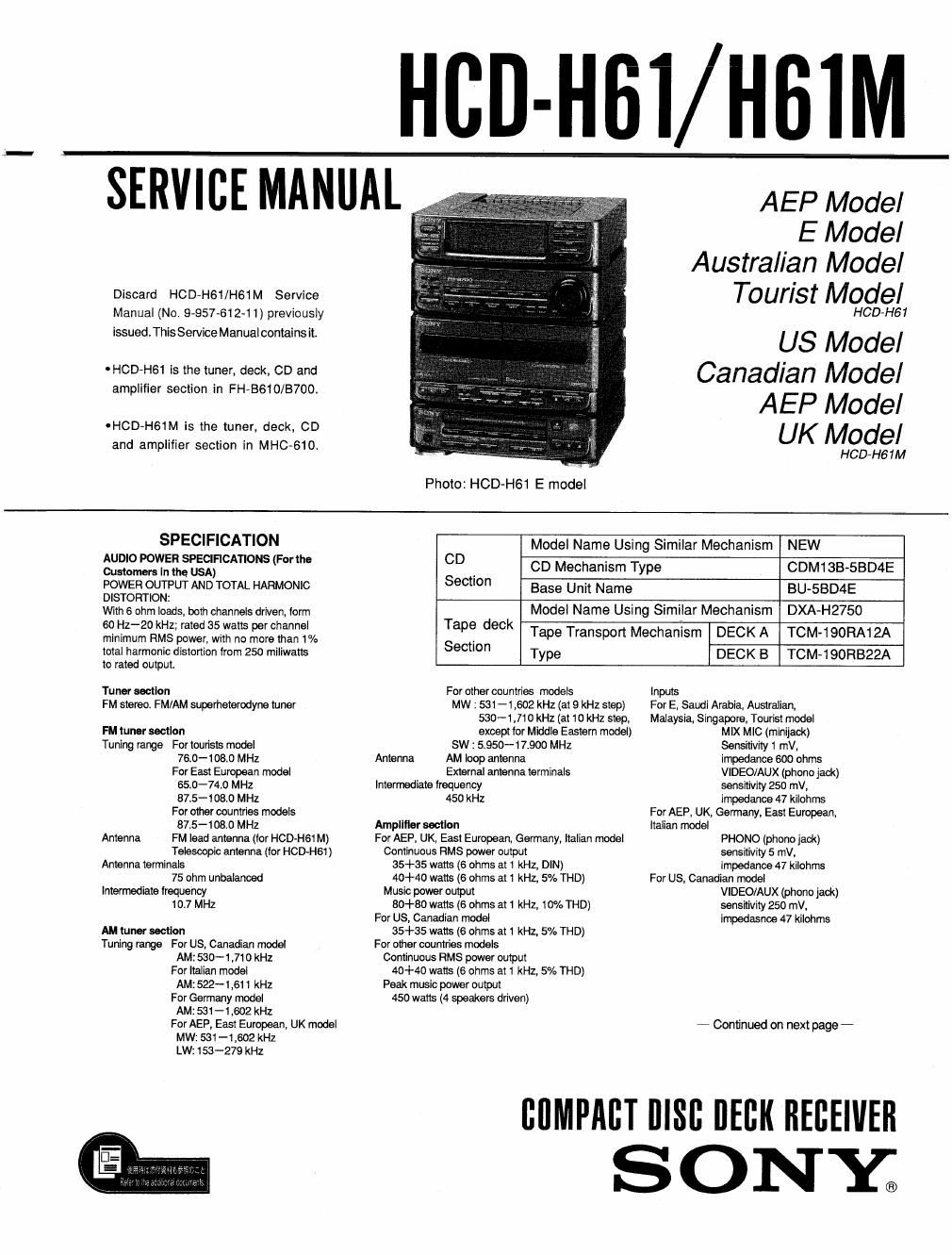
Extracted text from sony hcd h 61 (Ocr-read)
Page 2
Outputs
HEADPHONES (stereo minijank):
accept headphones of8 ohms
or more.
SPEAKERS: accept impedance cl 6 to
16 ohms
SURROUND SPEAKER (only for E,
Saudi Arabia, Australian, Malaysia,
Singapore, Tourist):
accept impedance of 8 to 16 ohms.
Cassette deck section
Recording system
radii 2»ohanne| stereo
Frequency response
(DOLBY NR OFF)
60-13900 HZ (14:3 dB),
using TYPE I
cassette (Sony HF-S)
60-14900 Hz (:3 dB),
using TYPE II
cassette (Sony UX-S)
Wow and Ilutler
0.1% WRMS i 03% (DIN)
Compact disc player section
System Compact disc digital audio systme
Laser Semiconductor laser
Wavelength=780-79O nm
General
Destination Power Power I
requlrements oonsumptlon
US, Canadian 120V Ac, (5on 100 watts
AEP, G, IT, EE 220-230V AC, SOIGOHZ 110 watts
240W
UK 240V AC, 50Hz
Australian 130W
110-120V/220-240V AC
5' EA' MY' SP' JE adjustable, 50/60Hz 13° ans
.AUS : Australian model
EA : Saudi Arabia model
G : Germany model
EE : East European model
IT : Italian model
MY : Malaysia model
SP : Singapore model
JE : Tourist model
Dimensions
Approx 225 X 285 X 265 mm (w/h/d)
(8% X11 Z ><1o /, inches)
incl, projecting pans and controls
Mass Approx. 63 kg (14 lb 5 oz)
Design and specifications subject to change
without notice.
Note
This appliance conforms with EEO Directive
87flO8/EEC regarding interference suppression.
Dolby noise reduction manufactured under license from
Dolby Laboratories Licensing Corporation,
DO LBY~and the double-D symbol DI] are trademarks of
Dolby Laboratories Licensing Corporation
TABLE OF CONTENTS
Section Title Page
SECTION 1. SERVICING NOTE ------------------------------- 5
SECTION 2. GENERAL
Parts Identification
Clock Setting'
Audio Adjustment
CD Playing ......................................................... 7
Radio
Tape Playback
Using the Graphic Equalizer
Recording ............................................................ 1]
Tape Dubbing ~-
CD Recording ~-
Timer-Activatcd Operation -
Microphone Mixing ............................................. 14
Singing AlOng ...................................................... 14
SECTION 3. DISASSEMBLY
3.1' Case Removal ...................................................... 15
3-2. Power Block Removal ---------------
3.3. MAIN Board Removal
3-4. CD Mechanism Block Removal
3-5. TC Mechanism Block Removal --------------------------- 17
SECTION 4. MECHANICAL ADJUSTMENTS --------- 18
SECTION 5. ELECTRICAL ADJUSTMENTS --------- 18
SECTION 6. DIAGRAMS
6-]. Block Diagram
6-2. Circuit Boards Location -
6-3. Semiconductor Lead Layouts --------------------------------- 32
6-4. IC Block Diagrams
6-5. Printed Wiring Board -MAIN SectionA
6-6. Schematic Diagram -MA1N Section- -
6-7. Printed Wiring Boards -TC Section- ----------------- 46
6-8r Schematic Diagrams -TC Section N
6-9. Schematic Diagrams -DISPLAY Section-
640. Printed Wiring Boards wDISPLAY Section-
6-11. Schematic Diagrams -CD Section- -------------------- 62
6-12. Printed Wiring Boards -CD Scction- ---------------- 65
SECTION 7. EXPLODED VIEWS
7-1. Case. Power Section
7-2r Front Panel Section
7-3. Mechanism Deck Chassist Section
67
68
~ 69
7»4. Mechanism Dock Section-1 '70
7-5. Mechanism Section-2 '71
7-6. CD Mechanism Section-1 ----------------------------------- 72
7-7, CD Mechanism Deck Section-2 -------------------------- 73
SECTION 8. ELECTRICAL PARTS LIST ~~~~~~~~~~~~~~~ 74