Sony hcd h 600 service manual
This is the 69 pages manual for sony hcd h 600 service manual.
Read or download the pdf for free. If you want to contribute, please upload pdfs to audioservicemanuals.wetransfer.com.
Extracted text from sony hcd h 600 service manual (Ocr-read)
Page 1
HCD-
HlBfl/HBUU
SERVICE MANUAL
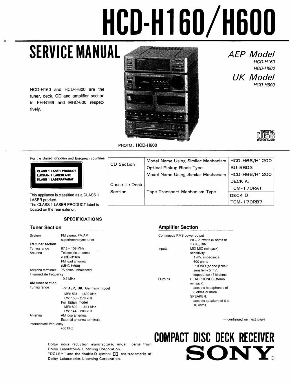
HCD-H160 and HCD-HGOO are the
tuner, deck, CD and amplifier section
in FH-B166 and MHC-600 respec-
tively.
AEP Model
HCD-H160
HCDvH600
UK Model
HOD-H600
coupon
anInL mom
PHOTO : HCD-H600
h U'tadKl dum ndE t'es . . . i
F0 8 m ng a roman mm" CD 5 12 Model Name Usmg Similar Mechanism HCD-H66/H1200
ec lOn
Optical Pickup Block Type BU-SBD3
Model Name Using Similar Mechanism HCD-H66/H1200
DECK A:
Cassette Deck
. , TCM-l 7ORAl
y . ,. Section Tape Transport Mechanism Type
This appliance Is classified as a CLASS 1 DECK B:
LASER product.
The CLASSl LASER PRODUCT label is TCM 1 7ORB7
located on the rear exterior.
SPECIFICATIONS
Tuner Section Amplifier Section
System FM stereo, FM/AM Continuous RMS power output
superheterodyne tuner 20 + 20 watts (6 ohms at
FM tuner section 1 kHz, DIN)
Tuning range 87.5 - 108 MHz Inputs MIX MIC (minijacki:
Antenna Telescopic antenna sensitivity
(HCD
(MHC-HSOO) PHONO (phono jacks):
Antenna terminals 75 ohms unbalanced sensitivity 5 rnVv
Intermediate frequency impedance 47 kilohms
10.7 MHz Outputs HEADPHONES (stereo
AM tuner section minijack):
Tuning range For AEP, UK, Germany model accepts headphones 01
MW: 531 -1,602 kHz 8 °th 9 mm
LW: 153 - 279 kHz SPEAKER-
For Italian model accepts speakers of 6 to
MW: 522 -1,e11 KHZ 6 ms
LW:144 - 288 kHz
Antenna AM loop antenna,
External antenna terminals
intermediate lrequency
450 kHz
Dolby noise reduction manufactured under license from
Dolby Laboratories Licensing Corporation.
"DOLBY" and the double-D symbol DU are trademarks of
Dolby Laboratories Licensing Corporation.
- continued on next page -
COMPACT DISC DECK RECEIVER
S 0 NY;
Page 2
HCD-H1 60/H600
Compact Disc Player Section
System Compact disc digital audio
system
Laser Semiconductor laser
(A = 780 nm)
Emission duration:
continuous
Max. 44.6 uW*
* This output is the value
measured at distance of
about 200 mm from the
objective lens surtace on
the Optical Pick-up Block.
Laser output
Cassette Deck Section
Recording system 4-track 2-channel stereo
Frequency response (DOLBY NFI OFF)
40 -1a,ooo Hz(18 dB),
using TYPE 1 cassette
(Sony HF»S)
40 -14.000 Hz (:3 dB),
using TYPE ll cassette
Wow and flutter 0.1% WRMS 10.3% (DIN)
General
Power requirements AEP model:
220 - 230 V, 50/60 HZ
U K model: 240 V, 50 Hz ,
Germany, Italian model: 240V AC, 50H:
Power consumption Except lor model: 90 watts
U K model: 160 watts
Approx. 615 x 285 x 250 mm
(w/h/d)
(24V: X11/4 >< 10% inches)
incl. projec1ing parts and
controls
Weight Approx. 12.6 kg (27 lb 12 oz)
Supplied accessories
Remote commander (RM-S100) (1)
Sony SUM-3 (NS)
batteries (2)
AM loop antenna (1)
FM lead antenna (1) (HCD-
HGOO only)
Dimensions
Design and specifications subject to change
without notice.
Note
This appliance conforms With EEC Directive
87/308/EEC regarding interierence suppression.
TABLE OF CONTENTS
Swift-n fltLe figs:
SECTION 1 SERVICING NOTES .................................... 3
SECTION 24 GENERAL
SECTION 3_ DISASSEMBLY ....................................... 21
SECTION 4. BLOCK DIAGRAM
4.,_ Mai Block ................................................... 23
44, CD Block ................................................. 25
SECTION 5. MECHANICAL ADJUSTMENT
SECTION 6. ELECTRICAL ADJUSTMENT --------------------- 29
SECTION 7. DIAGRAMS
7.1_ Semiconductor Lead by; .............................. 35
7.2» cm, Boards Location .................................... 36
73. Printed Wiring;I Boards-TunerIDeck/CD Section-"- 39
7-4. Schematic Diagrams-Tuner/Deck Section- --------- 43
7-5. Schematic Diagrams
~Powu/Amplifier/Display Section~ - ----------- 47
76. Printed Wiring Boards
-Power/Amplifier/Display Section - ............ 51
7»7. Schematic Diagrams -CD Section - ------------------ 54
7.3_ Pin Functions ................. . ................................. 61
SECTION 8. EXPLODED VIEWS
8~1i Case, Power Section - 67
8-2. Front Panel. Main Board Section ............. 68
3.3. MD Giassis Section .......................................... 69
8.4. Mechanism Deck Section (1) .............................. 70
8-5, McChanism Deck Section (2) .................. . ........... 71
8-6. CD Section (1)
3.7, CD Section (2) ................................................ 73
SECTION 9. ELECTRICAL PARTS LIST ---------------------- 74
SAFETY-RELATED COMPONENT WARNING
COMPONENTS IDENTIFIED BY MARK A OR DOTTED
LINE WITH MARK A ON THE SCHEMATIC DIAGRAMS
_AND IN THE PARTS LIST ARE CRITICAL TO SAFE
OPERATION.
REPLACE THESE COMPONENTS WITH
SONY PARTS WHOSE PART NUMBERS APPEAR AS
SHOWN IN THIS MANUAL OR IN SUPPLEMENTS PUB-
LISHED BY SONY.