Sony hcd h 51 k fhb500 k sm sd
This is the 41 pages manual for sony hcd h 51 k fhb500 k sm sd.
Read or download the pdf for free. If you want to contribute, please upload pdfs to audioservicemanuals.wetransfer.com.
Extracted text from sony hcd h 51 k fhb500 k sm sd (Ocr-read)
Page 1
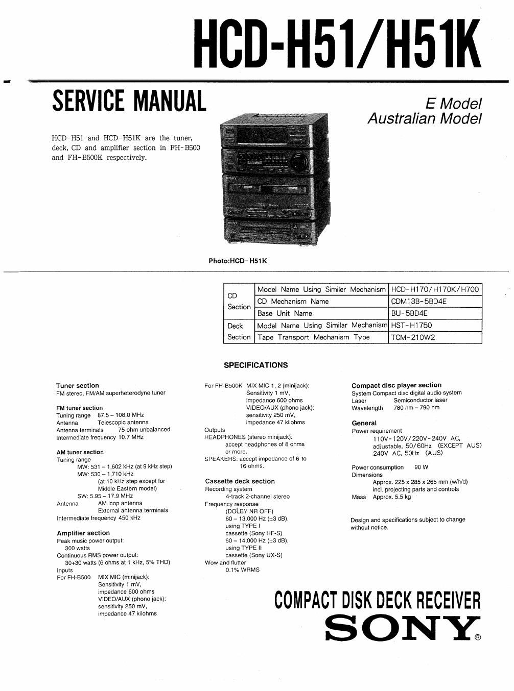
HGD-H51/ H5IK
SERVICE MANUAL ' . { Mode,
Australian Model
HCD-H51 and HCD-H51K are the tuner,
deck, CD and amplifier section in FH-B500
and FH-BSOOK respectively.
PhotozHCD- H51 K
Model Name Using Similer Mechanism HCD-HI70/H170K/H7OO
CD Mechanism Name CDMI3B-5BD4E
Base Unit Name BU-SBD4E
Deck Model Name Using Similar Mechanism HST-H1750
Section Tape Transport Mechanism Type TCM-ZlOWZ
CD
Section
SPECIFICATIONS
Tuner section For FH»B500K MIX MIC 1, 2 (minijack): Compact disc player section
FM Stereov IM/AM superheterodyne tuner Sensitivity 1 mVr System Compact disc digital audio system
impedance 500 ohms Laser Semiconductor laser
FM tuner section VIDEO/AUX (phone jack): Wavelength 780 nm - 790 nm
Tuning range 87.5 - 108.0 MHz sensitivity 250 mV,
Antenna Telescopic antenna impedance 47 kilohms GeneraI
Antenna terminals 75 ohm unbalanced Outputs Power requirement
Intermediate irequency 10.7 MHZ HEADPHONES (stereo minijack): 110V-120V/220V- 240V AC,
accept headpmm 0 3 °th adjustable, 50/ 60Hz (EXCEPT AUS)
AM tuner section or more. 240V AC. 50H: (AUS)
Tuning range SPEAKERS: accept impedance cl 6 to
MW: 531 - 1,602 kHz (at 9 kHz step) 16 ohms. power consumption 90 w
MW: 530 - 1,710 kHz Dimensions
(at 10 kHz step except for Cassette deck section Approx. 225 x 285 x 265 mm (w/h/d)
Middle Eastern model) RECOMINQ 51/816!" incl. projecting pans and controls
SW: 5.95 - 17.9 MHz 4»track 2-channel stereo Mass Approx. 5.5 kg
Antenna AM loop antenna Frequency response
External antenna terminals (DOLBY NH OFF)
Intermediate frequency 450 KHZ 6° 13-000 HZ (13 dB), Design and specifications subject to change
. using TYPE I without notice.
Amplifier section cassette (Sony HF-S)
Peak music power output: 60 - 14,000 Hz (:3 dB).
300 watts using TYPE Ii
Continuous RMS power output: cassette (Sony UX-S)
30+30 walls (6 ohms at 1 kHz, 5% THD) Wow and llutter
Inputs 0,1% WHMS
For FH-BSOO MIX MIC (minijack):
Sensitivuy 1 mV.
COMPACT DISK DECK RECEIVER
S ONY;
Page 2
To prevent fire or shock hazard, do not expose the unit to rain or
moisture.
To avoid electrical shock, do not open the cabinet. Refer servicing to
qualified personnel only
Laser component in this product is capable of emitting radiation
exceeding the limit for Class 1.
CLASS I LASER PRODUCT
LUOKAN I LASEHLAITE
KLASS I LASERAPPAFIAT
This appliance is classified as 3 CLASS 1 LASER PRODUCT
MARKING is located on the rear exterior.
The following caution label is located inside the unit.
mam use: gum wm om
CAUT|ON AVOlD EXPOSURE YD
usmLiG LISERSYHAUN a van Lemma MAR
ADVARSEL leKERNEDsAFIanERE an unsmm mow
wDGA ms EVELSE FOR sin
I -AvAmt:ssA a sumALuKIms mamas;
VARO' 'DtiT ALI'IflNA USEMHEl LVLLE
:LASERSVRALING MAR DENNA DEL Ni OFPNAD
VARN|NG 00K SPARREN AR UR!
min. NA SE APNES
ADVARSEL eaten l
SAFETV-RELATED COMPONENT WARNING
COMPONENTS IDENTIFIED BY SHADING AND MARK
A ON THE SCHEMATIC DIAGRAMS AND IN THE
PARTS LIST ARE CRITICAL TO SAFE OPERATION.
REPLACE THESE COMPONENTS WITH SONY PARTS
WHOSE PART NUMBERS APPEAR AS SHOWN IN THIS
MANUAL OR IN SUPPLEMENTS PUBLISHED BY SONY.
TABLE OF CONTENTS
M M has
1 SERVIC|NG NOTE ................................... 3
2. GENERAL .......................................... 5
3. DISASSEMBLY ...................................... 6
4. MECHANICAL ADJUSTMENTS ....................... 9
5. ELECTRICAL ADJUSTMENTS ........................ 9
6. DIAGRAMS
6-1. Semiconductor Lead Layouts.
-15
-16
6-2. Circuit Boards Lcation
6-3. Schematic Diagram -Tuner Section- - 17
6-4. Schematic Diagram -BD Section- ---------- 19
6-5. Schematic Diagram -Main Section- -------- 23
6-6. Printed Wiring Boards -Main Section- 27
6-7. Printed Wiring Boards -Display Section-~~ 32
6-8. Schematic Diagram -Display Section- ..... 35
7. EXPLODED VIEWS
7- 1. Case, Power Board Section ------------------- 41
7-2. Front Panel, Main Board Section ------------ 42
743. Mechanism Section-1 (TCM-ZIOWZ) -------- 43
7-4. Mechanism Section-2 (TCM-ZIOWZ) ........ 44
745. CD Section-1 (CDMlZB-EBDAE) ------------ 45
7-6. CD Section-2 (BU-5BD4E) ------------------ 46
B. ELECTRICAL PARTS LIST ~ ' ---------------------- 47