Sony hcd h 170 service manual

This is the 77 pages manual for sony hcd h 170 service manual.
Read or download the pdf for free. If you want to contribute, please upload pdfs to audioservicemanuals.wetransfer.com.

Page: 1 / 77
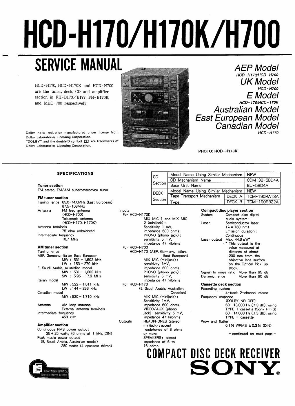
sony hcd h 170 service manual

Extracted text from sony hcd h 170 service manual (Ocr-read)


Page 2

HCD- H170/H170K/H700

Speaker section

Speaker system 3 way system

Speaker units
Woofer: 13 cm dia.. cone type
Tweeter: 5 cm dia., cone type
Super tweeter: 2 cm dia., dome

type
Enclosure Bass reflex
Frequency range 60 Hz - 20 kHz
Sensitivity 88 dB/wlm
Flated impedance 6 ohms
Dimensions Approx. 195 x 285 x 230 mm
(7 518x11 1/4 x 9 inches)
Weight Approx. 3.0 kg (6 lb 10 oz)
net per speaker
General
Desti- Power Power
nation requirements consumption
AEP, Italianv
Germany, 220- 230V
East European Ac, 50/60 Hz 8° watts
model
UK 240V AC.
model 50 Hz 160 watts
E IOOV-I20V
' . . or 220V-
iiufmmb'a 240v AC 80 watts
Eel ran adjustable.
"° 50/6014:
Canadian i20V AC.
model 60H: 80 watts
Dimensions
Approx. 225 x 285 x 268 mm
(w/h/d)

(8 7/8x111/4x10 5/8 inches)
incl. projecting parts and controls
Weight
Approx. 6.2 kg (13 lb 11 oz)
Accessories supplied
AM loop antenna (1)
Remote commander (1)
Sony SUM~3 (NS) batteries (2)
FM lead antenna (1) (HCD-H7OO only)
Speaker cords (2)
(HCD-H700, except for the UK
model)

Design and specifications subject to
change without notice.

Note

This appliance conforms with EEC
Directive 87/308/EEC regarding
interference suppression.

This appliance is classified as 3
CLASS 1 LASER product.

CLASS 1 LASER PRODUCT

LUOKAN 1 LASERLAITE The CLASS I LASER PRODUCT

Kass , 55,;me label Is located on the rear

exterior.

TABLE OF CONTENTS
Section Title Page
1.8EFIVICINGNOTES-m-u-u-u ..................... 3
LGENERAL - . 5
3. DISASSEMBLY
3-1. Case .............................. ............25
3-Z.PowerB10ck u......~...H............ ....... 25
3- 3, Main Board ................................... 25
3-4, CD Mechanism Block 26
3-5. TC Mechanism Block ~ ~ ' ~ - - - 27
3-6. Volume/ MIC HP/ Display/ SW Board . ' 27
4. MECHANICAL ADJUSWENTS ~~~~~~~~~~~~~~~~~~~~~~ 28
5. ELECTRICAL ADJUSTMENTS --------------------- 28
8. DIAGRAMS
6- 1. Semiconductor Lead Layouts - - 34
6- 2. Circuit Boards Location ~ - ~ . . - 35
6-3. Printed Wiring Boards -Main Section- ----- 37
6-4. Schematic Diagram --Main Section- --------- 41
6-5. Schematic Diagram -Sub Section- --------- 46
6-6. Printed Wiring Boards --Sub Section- ------ 51

6-7, Printed Wiring Boards -Display Section---- 56

6-8. Schematic Diagram -Display Section- ------ 59
. . . . . . . . . 62

6-9. Schematic Diagram -BD Section
6- 10. IC Pin Description ~ ~ - -

7. EXPLODED VIEWS

7- 1, Case, Power Section .. . . . ...... . . . ............ 71
7-2. Front Panel, Main Board Section 72
7-3, MD Chassis Section ........................... 73
7-4. Mechanism Deck Section (1) 74
7-5. Mechanism Deck Section (2) ~ 75

- 76

- 77
a. ELECTRICAL pAm-s LIST .......................... 78

SAFETY-RELATED COMPONENT WARNINGH

COMPONENTS IDENTIFIED BY MARK A OR DOTTED
LINE WITH MARK A ON. THE SCHEMATIC DIAGRAMS
AND IN THE PARTS LIST ARE CRITICAL TO SAFE
OPERATION. REPLACE THESE COMPONENTS WITH
SONY PARTS WHOSE PART NUMBERS APPEAR AS
SHOWN IN THIS MANUAL OR IN SUPPLEMENTS PUB-
LISHED BY SONY.