Sony hcd h 1000

This is the 17 pages manual for sony hcd h 1000.
Read or download the pdf for free. If you want to contribute, please upload pdfs to audioservicemanuals.wetransfer.com.

Page: 1 / 17
sony hcd h 1000

Extracted text from sony hcd h 1000 (Ocr-read)


Page 1

HCD-HICDC

SERVICE MANUAL

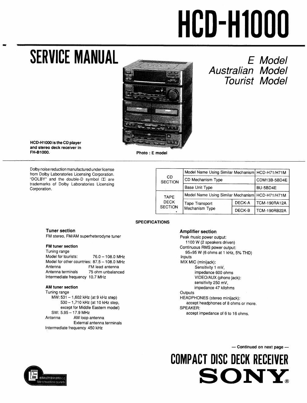
HCD-H1 000 is the CD player
and stereo deck receiver In

E Model
Australian Model
Tourist Model

FH-B1000. Photo : E model
Dolby noisereduotion manufactured underlicense t . . t
from Dolby Laboratories Licensing Corporation CD Model Name Using Similar Mechanism HCD»H71/H71M
DOLBV and the double»D symbol D0 are CD Mechanism Type CDM1SB-5BD4E
SECTION
trademarks of Dolby Laboratories Licensing B U 't T BU BD4E
Corporation ase n1 ype -5
TAPE Model Name Using Similar Mechanism HCD-H71/H71M
DECK Tape Transport DECK-A TCM-190RA12A
SECTIO? MeChanism Type DECK-B TOM-190R322A
SPECIFICATIONS

Tuner section
FM stereo, FM/AM superheterodyne tuner

FM tuner section

Tuning range

Model for tourists: 76,0 - 108.0 MHz
Model Ior other countries: 875 - 108.0 MHz
Antenna FM lead antenna
Antenna terminals 75 ohm unbalanced
Intermediate frequency 10.7 MHz

AM tuner section
Tuning range
MW: 531 - 1,602 kHz (at 9 kHz step)
530 - 1.710 kHz (at 10 kHz step,
except for Middle Eastern model)
SW: 5,95 -173 MHz
Antenna AM loop antenna
External antenna terminals
Intermediate frequency 450 kHz

Amplifier section
Peak rnuslc power output:
1100 W (2 speakers driven)
Continuous RMS power output:
95+95 W (6 ohms at 1 kHz, 5% THD)
Inputs
MIX MIC (minijack):
Sensitivity 1 mV,
impedance 600 ohms
VIDEO/AUX (phone jack):
sensitivity 250 mV,
Impedance 47 kilohms
Outputs
HEADPHONES (stereo minijack):
accept headphones of 8 ohms or more.
SPEAKER:
accept impedance of 6 to 16 ohms.

- Continued on next page -

COMPACT DISC DECK RECEIVER

SONY;

Page 2

SECTION 6
IC PIN FUNCTIONS

o IC401 Deck Controller (M50964-280FPIO (T C board)

Pin No Pin Name I/O Symbol Description
1 P62 G GND
2 P61 G GND
3 P60 G GND
4 P47 G +5V
5 P46 G +5V
Deck 8 record prevention claw A. B detection input (Analog)
Volgate (V) 1V 1.9V 2.8V 39V 5V
6 ANS I B HALF Half ON ON ON ON OFF
E. PROOF A OFF ON OFF ON OFF
E. PROOF B ON ON OFF OFF OFF
7 AN4 1 KEY Y KEY "'9"
Volgate (v) o as 0.7 L2 L7 2.3 23 3.4 4.0 4.5 5.0
KEY Y El BII a» 34 A« A» neuvorr
8 ANS I KEY X KEY X Al A» A4 B« B» E. DUB co
9 AN2 I AMS IN AMS signal input
10 P41 0 L MUTE Line mute output
11 P40 O m mute output
12 P37 0 RELAY (B MD) REC/PB change relay output
13 P36 0 R/P Dolby IC REC/PB select output
14 P35 0 EQ70 Playback EQ output for playing deck (Not Used)
l5 P34 0 SEL A/R Dolby IC PB input Deck A/B select output
16 P33 0 AMS A/D AMS AMP input Deck A/B select output (Not Used)
17 P32 I AU BUS AUDIO BUS input
18 P31 0 BIAS Bias oscillation output
19 P80 0 AUB OUT AUDIO BUS output
20 INTI I A BUS AUDIO BUS normal input
21 NC - - ~-
22 NC - - -
23 NC - - -
24 V55 V85 GND
25 R-ESE-T I RE ET Microcomputer reset input
26 XIN I XIN Clock input (4MHZ)
27 X0 0 XOUT Clock output (4Mllz)
28 CD 0 to Not used (open)
29. 65 V55 V55 GND
30 P57 I PW IN POWER OFF detection input
31 P56 I A STOP Deck A STOP switch input
32 P55 1 Am Deck A Half switch input
33 P54 I A SHUT Deck A Reel table signal input
34 P53 I A70 U Deck A TYPE II switch input (Not Used)
35 P52 I B STOP Deck B STOP switch input
36 P51 I B SHUT Deck B Reel table signal input
37 P50 1 B70 U Deck B TYPE II switch input (Not Used)
38 NC ~ --
39 P17 0 ARM 3 Deck A Reel Motor control out
40 P16 0 ARM 2 Deck A Reel Motor control out