Sony hcd gsx 100 w service manual

This is the 72 pages manual for sony hcd gsx 100 w service manual.
Read or download the pdf for free. If you want to contribute, please upload pdfs to audioservicemanuals.wetransfer.com.

Page: 1 / 72
sony hcd gsx 100 w service manual

Extracted text from sony hcd gsx 100 w service manual (Ocr-read)


Page 1

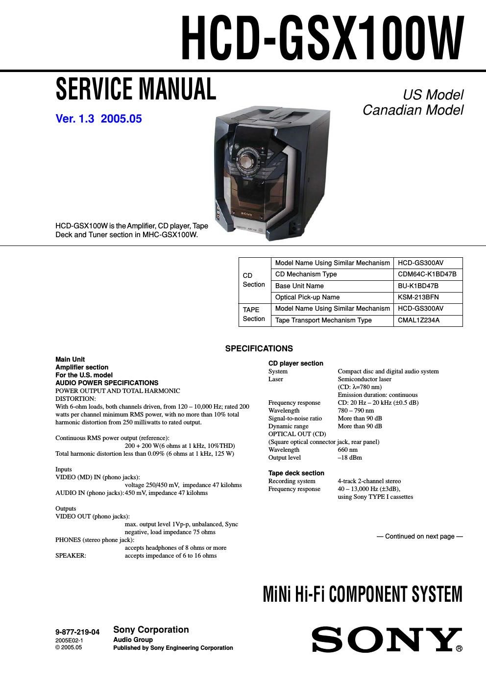
HCD-GSX100W

SERVICE MANUAL

Ver. 1.3 2005.05

HCD-GSX1 cow is theAmplifier, CD player, Tape
Deck and Tuner section in MHC-GSX100W.

US Model
Canadian Model

Model Name Using Similar Mechanism HCD-GS300AV
CD CD Mechanism Type CDM64C-K1BD47B
Section Base Unit Name BU-KtBD47B
Optical Pick-up Name KSM-213BFN
TAPE Model Name Using Similar Mechanism HOD-G3300AV
Section Tape Transport Mechanism Type CMAL1Z234A

SPECIFICATIONS

Main Unit

Amplifier section

For the us. model

AUDIO POWER SPECIFICATIONS

POWER OUTPUT AND TOTAL HARMONIC

DISTORTION:

With 6-ohm loads, both channels driven, from 120 - 10,000 Hz; rated 200
watts per channel minimum RMS power, with no more than 10% total
harmonic distortion from 250 milliwatts to rated output.

Continuous RMS power output (reference):
200 + 200 W(6 ohms at 1 kHz, 10%THD)
Total harmonic distortion less than 0.09% (6 ohms at 1 kHz, 125 W)

Inputs
VIDEO (MD) IN (phono jacks):

voltage 250/450 mV, impedance 47 kilohms
AUDIO IN (phono jacks):450 mV, impedance 47 kilohms

Outputs
VIDEO OUT (phono jacks):
max. output level le-p, unbalanced, Sync
negative, load impedance 75 ohms
PHONES (stereo phone jack):
accepts headphones of 8 ohms or more

SPEAKER: accepts impedance of 6 to 16 ohms
59.377.219.04 Sony Corporation

2005E0271 Audio Group

©2005.05 Published by Sony Engineering Corporation

CD player section
System
Laser

Compact disc and digital audio system
Semiconductor laser

(CD: #780 nm)

Emission duration: continuous

Frequency response CD: 20 Hz - 20 kHz (:05 dB)

Wavelength 780 - 790 nm
Signal-to-noise ratio More than 90 dB
Dynamic range More than 90 dB
OPTICAL OUT (CD)

(Square optical connector jack, rear panel)
Wavelength 660 nm

Output level -1 8 dBm

Tape deck section
Recording system
Frequency response

4-track 2-channel stereo
40 -13,000 Hz (:SdB),
using Sony TYPE I cassettes

- Continued on next page -

Milli Hi-Fi COMPONENT SYSTEM
S ONE;

Page 2

HCD-GSX1OOW
Ver1.1 2003.09

Tuner section
FM stereo, FM/AM superheterodyne tuner
FM tuner section
Tuning range

Antenna

Antenna terminals
Intermediate frequency
AM tuner section
Tuning range

87.5 - 108.0 MHz
FM lead antenna

75 ohms unbalanced
10.7 MHz

530 - 1,710 kHz

(with the tuning interval set at 10 kHz)

531 - 1,710 kHz

(with the tuning interval set at 9 kHz)
Antenna AM loop antenna, external antenna terminal
Intermediate frequency 450 kHz

Transmitter

Carrier frequency 913.5 - 914.5 MHz
Channel

CHANNEL]: 913.5 MHz
CHANNELZ: 914.0 MHz
CHANNEL3: 914.5 MHz
Modulation FM stereo

Power source DC 9 V: supplied AC power adaptor

(AC-GSXIOO)

General
Power requirements: 120 V AC, 60 Hz
Power consumption: 170 W

Dimensions (w/h/d) incl. projecting parts and controls Amplifier/Tuner]
Tape/CD section: Approx. 280 x 326 x 490 mm

Transmitter Approx. 136 x 100 x 103 mm

Mass: Approx. 11.5 kg

Transmitter Approx. 146 g

Supplied accessories Remote (1)

size AA (R6) batteries (2)
AM loop antenna (1)

PM lead antenna (1)
Transmitter (1)

AC adaptor (1)

Connecting cord phone
plug-stereo miniplug (1m) (1)

Design and specifications are subject to change without notice.

TABLE OF CONTENTS

Audio input phono jacks/stereo mini jack
1. SERVICING NOTES ....................................................... 4
2_ GENERAL .......................................................................... 5

3. DISASSEMBLY
3-1. Top Cabinet .,
3-2. Front CabiASSY-
3-3. Back PanelASSY

3-4. Detect Board, Main Board '9
3-5. Amp Board 10
3-6. Power Board ~ 10

3-7. Holder (LED-S), Middle (R), Power Bracket ,
,. 11

3-8. CD Mechanism Deck (CDM64C-K1BD47B)
3-9. Base Unit (BU-K1BD47B),

D-Sensor (OUT) Board, T»Sensor Board -------------------- 12
3-10. D-Sensor (IN) Board, Load SW Board,

LT Motor Board 12
3-11. CD LED Board 13
3.12311 Holder ASSY ........................................ ,. 13

-- 14

3-13. CD Board, Optical Pick-up (KSM-213BFN) -
3-14.RX-Base PC Board ASSY,

Mechanical Deck (CMAL1Z234A), Cassette Holder 14
3.15 Game Board, pm: Board .............................................. 15
3-16. Display Board .......................... 15
,. 16

3-17.KEY (2) Board, CD Sync Button ,

3-18.KEY Board, Wireless Board ........................................ 16
4_ TEST MODE .................................................................... 17
5. MECHANICAL ADJUSTMENTS ............................. 1g
6. ELECTRICAL ADJUSTMENTS .............................. 1g

7. DIAG RAMS
7-1. Circuit Boards Location .
7-2. Block Diagrams «
~ CD Section A ,.
-- Tuner/Tape Deck Section E
- INPUT/EVR Section -
~Amp Section _ ....................
~ Display/Power Supply Section ~
7-3. Printed Wiring Board 4 CD Section -
7-4. Schematic Diagram ~ CD Section -~
7-5. Printed Wiring Board

_ CD Motor/Sensor Section _ ..................................... 30

7-6. Schematic Diagram

- CD Motor/Sensor Section -
7-7. Printed Wiring Board 4 Main Section ~
7-8. Schematic Diagram ~ Main Section (1/3)
7-9. Schematic Diagram A Main Section (2/3)
7-10. Schematic Diagram ~ Main Section (3/3)
7-11. Printed Wiring Board ~ Amp Section
7-12. Schematic Diagram ~ Amp Section _
7-13.Printed Wiring Board 4 Display Section 4
7-14. Schematic Diagram ~ Display Section ~ ~-
7-15. Printed Wiring Board 4 Key Section --
7-16. Schematic Diagram ~ Key Section
7-17. Printed Wiring Board 4 Power Section 4
7-18. Schematic Diagram ~ Power Section
7-19.Printed Wiring Board 4 RX Section A
7-20. Schematic Diagram ~ RX Section -
7-21.1C Block Diagrams
7.2211(3 pm Function Description ........................................ 4g


8. EXPLODED VIEWS

3.11 General Section ........................................................... 53
- 54
, 55

8-2. Front Panel Section
8-3. Chassis Section rrrrr
8-4. Mechanism Deck Section-1 (CDM64C-K1BD47B) 56
8-5. Mechanism Deck Section-2 (CDM64C-K1BD47B
8-6. Base Unit Section (BU-KlBD47B)

9. ELECTRICAL PARTS LIST ....................................... 59

-24

-57
-58