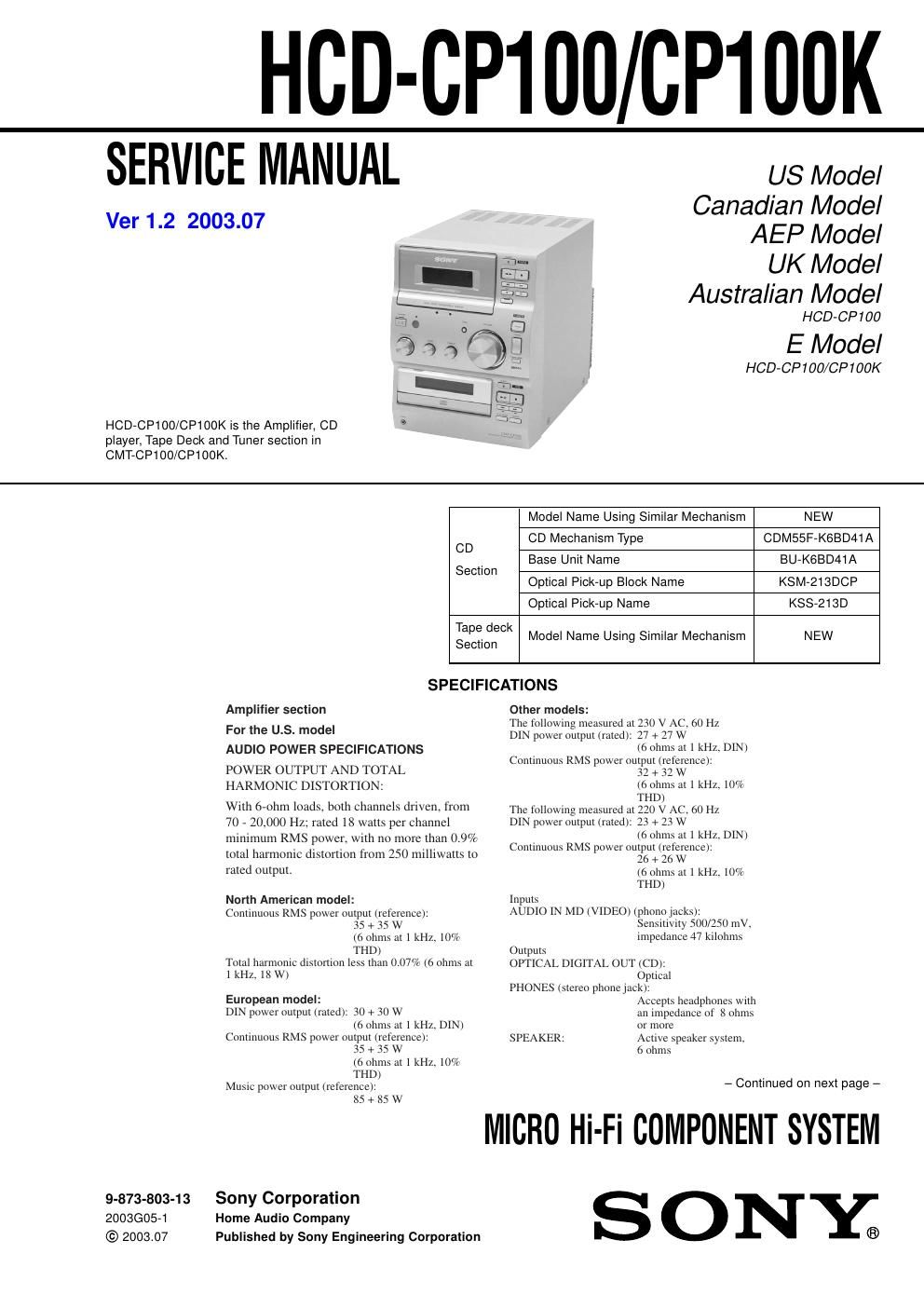
Sony hcd cp 100 k service manual
This is the 50 pages manual for sony hcd cp 100 k service manual.
Read or download the pdf for free. If you want to contribute, please upload pdfs to audioservicemanuals.wetransfer.com.
Extracted text from sony hcd cp 100 k service manual (Ocr-read)
Page 1
2 HCD-CP100/CP100K CD player section System Compact disc and digital audio system Laser Semiconductor laser (λ = 780 nm) Emission duration: continuous Wavelength 780 - 790 nm Frequency response 2 Hz - 20 kHz (±0.5 dB) Tape player section Recording system 4-track 2-channel stereo Frequency response 50 - 13,000 Hz (±3 dB), using a Sony TYPE I cassette Wow and flutter±0.15% W. Peak (IEC) 0.1% W. RMS (NAB) ±0.2% W. Peak (DIN) Tuner section FM stereo, FM/AM superheterodyne tuner FM tuner section Tuning range North American model: 87.5 - 108.0 MHz (100-kHz step) Other models: 87.5 - 108.0 MHz (50-kHz step) Antenna FM wire antenna Antenna terminals 75 ohm unbalanced Intermediate frequency 10.7 MHz AM tuner section Tuning range Pan-American model: 530 - 1,710 kHz (with the tuning interval set at 10 kHz) 531 - 1,710 kHz (with the tuning interval set at 9 kHz) European model: 531 - 1,602 kHz (with the tuning interval set at 9 kHz) Middle Eastern and Philippine models: 531 - 1,602 kHz (with the tuning interval set at 9 kHz) Other models: 530 - 1,710 kHz (with the tuning interval set at 10 kHz) 531 - 1,602 kHz (with the tuning interval set at 9 kHz) Antenna AM loop antenna, external antenna terminal Intermediate frequency 450 kHz General Power requirements North American model: 120 V AC, 60 Hz European model: 230 V AC, 50/60 Hz Australian model: 220 - 240 V AC, 50/60 Hz Mexican model: 120 V AC, 60 Hz Other models: 110 - 120 V or 220 - 240 V AC , 50/60 Hz Adjustable with voltage selector Power consumption European model: See the nameplate 0.5 W (in the standby mode) Other models: See the nameplate Dimensions (w/h/d) Approx. 190 × 252 × 345 mm incl. projecting parts and controls Mass Approx. 5.6 kg Design and specifications are subject to change without notice. TABLE OF CONTENTS 1. SERVICING NOTES ............................................... 4 2. GENERAL Location of Controls ....................................................... 5 Setting the Time .............................................................. 6 3. DISASSEMBLY 3-1. Disassembly Flow ........................................................... 7 3-2. Cover (Upper) ................................................................. 8 3-3. CD Lid ............................................................................. 8 3-4. Front Panel Section ......................................................... 9 3-5. Tape Mechanism Deck .................................................... 9 3-6. CD Mechanism Deck (CDM55F-K6BD41A) ................ 10 3-7. Base Unit (BU-K6BD41A) ............................................. 10 3-8. Loading Board ................................................................. 11 3-9. Cam (CDM55) ................................................................ 11 4. TEST MODE .............................................................. 12 5. ELECTRICAL ADJUSTMENTS Deck Section ................................................................... 13 CD Section ...................................................................... 13 6. DIAGRAMS 6-1. Block Diagram – CD SERVO Section – ........................ 14 6-2. Block Diagram – MAIN Section – ................................. 15 6-3. Block Diagram – DISPLAY/POWER SUPPLY Section – ...................... 16 6-4. Note for Printed Wiring Boards and Schematic Diagrams ....................................................... 17 6-5. Printed Wiring Board – CD Board – .............................. 18 6-6. Schematic Diagram – CD Board – ................................. 19 6-7. Printed Wiring Board – TC Board – ............................... 20 6-8. Schematic Diagram – TC Board – .................................. 21 6-9. Schematic Diagram – MAIN (1/2)/LOADING Board – ................................. 22 6-10. Schematic Diagram – MAIN Board (2/2) – ................... 23 6-11. Printed Wiring Board – MAIN Board – ......................... 24 6-12. Printed Wiring Boards – SWITCH/TC SWITCH/PRISM Boards – ................... 26 6-13. Schematic Diagram – SWITCH/TC SWITCH/PRISM Boards – ................... 27 6-14. IC Pin Function Description ........................................... 28 6-15. Printed Wiring Boards – LCD/HEADPHONE Boards – .................................... 29 6-16. Schematic Diagram – LCD/HEADPHONE Boards – ... 29 6-17. Printed Wiring Board – POWER Board – ...................... 30 6-18. Schematic Diagram – POWER Board – ......................... 31 7. EXPLODED VIEWS 7-1. Cover Section .................................................................. 35 7-2. Front Panel Section ......................................................... 36 7-3. Chassis Section ............................................................... 37 7-4. CD Mechanism Deck (CDM55F-K6BD41A) ................ 38 7-5. Base Unit (BU-K6BD41A) ............................................. 39 8. ELECTRICAL PARTS LIST ............................... 40