Sony hcd c 5 service manual

This is the 98 pages manual for sony hcd c 5 service manual.
Read or download the pdf for free. If you want to contribute, please upload pdfs to audioservicemanuals.wetransfer.com.

Page: 1 / 98
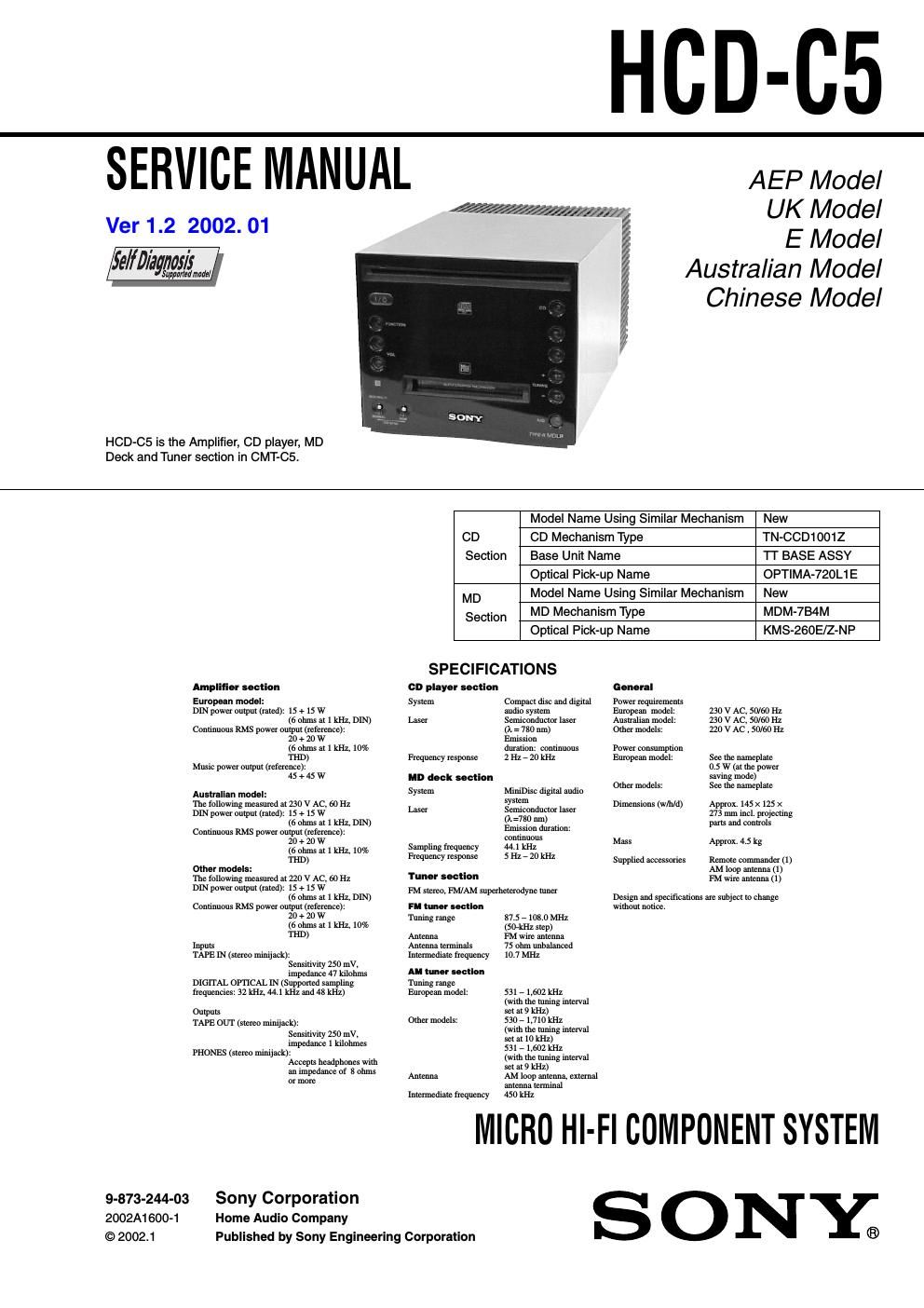
sony hcd c 5 service manual

Extracted text from sony hcd c 5 service manual (Ocr-read)


Page 1

2 HCD-C5 SELF-DIAGNOSIS FUNCTION The self-diagnosis function consists of error codes for customers, which are displayed automatically when errors occur, and error codes, which show the error history in the test mode during servicing. For details on how to view error codes for the customer, refer to the following box in the instruction manual. For details on how to check error codes during servicing, refer to the following Procedure for using the Self-Diagnosis Function (Error History Display Mode). Self-diagnosis display This system has a Self-diagnosis display function to let you know if there is a system malfunction. The display shows a code made up of 3 or 5 letters and a message alternately to show you the problem. To solve the problem refer to the following list. If any problem persists, consult your nearest Sony dealer. C11/Protected The MD is protected against erasure. cRemove the MD and slide the tab to close the slot (see page 18). C12/Cannot Copy You tried to record a CD or MD with a format that the system does not support, such as a CD-ROM. cRemove the disc and turn off the system once, then turn it on again. C13/REC Error Recording could not be performed properly. cMove the system to a stable place, and start recording over from the beginning. The MD is dirty or scratched, or the MD does not meet the standards. cReplace the MD and start recording over from the beginning. C13/Read Error The MD deck cannot read the disc information properly. cRemove the MD once, then load it again. E0101/LASER NG There is a problem with the optical pickup. cThe optical pickup may have failed. Consult your nearest Sony dealer. C14/Toc Error The MD deck cannot read the disc information properly. cReplace the MD. Erase all the recorded contents of the MD using All Erase Function (see page 29). C41/Cannot Copy The sound source is a copy of a commercially available music software, or you tried to record a CD-R (Recordable CD). cThe Serial Copy Management System prevents making a digital copy (see page 48). You cannot record a CD-R. C71/Check OPT-IN This appears momentarily because of the signal of the digital broadcast during recording. cThere is no affect on the recorded contents. No component is connected to the DIGITAL OPTICAL IN jack, or a digital component is not connected properly. cConnect a digital component to the DIGITAL OPTICAL IN jack properly using a digital connecting cable (not supplied, see page 43). The connected digital component is not turned on. cSee the operating instructions supplied with the connected component and confirm whether the component is turned on. The digital connecting cable connected to the DIGITAL OPTICAL IN jack is pulled out, or the connected digital component is turned off during digital recording. cConnect the cable, or turn on the digital component. E0001/MEMORY NG There is an error in the internal data that the system needs in order to operate. cConsult your nearest Sony dealer.

Page 2

3 HCD-C5 TABLE OF CONTENTS SELF-DIAGNOSIS FUNCTION ..................................... 2 1. SERVICING NOTES ............................................... 4 2. GENERAL ................................................................... 7 3. DISASSEMBLY ......................................................... 9 4. TEST MODE ............................................................... 24 5. ELECTRICAL ADJUSTMENTS CD Section ...................................................................... 33 MD Section ..................................................................... 34 6. DIAGRAMS 6-1. NOTE FOR PRINTED WIRING BOARDS AND SCHEMATIC DIAGRAMS ............................................ 45 – Wave forms ................................................................... 45 – Circuit Boards Location ............................................... 45 6-2. Block Diagram – CD Servo Section – ............................ 46 6-3. Block Diagram – MD Servo Section – ........................... 47 6-4. Block Diagram – MAIN Section – ................................. 48 6-5. Printed Wiring Boards – CD Section – .......................... 49 6-6. Schematic Diagram – CD Section – ............................... 50 6-7. Printed Wiring Board – BD (MD) Board – .................... 51 6-8. Schematic Diagram – BD (MD) Board (1/2) – .............. 52 6-9. Schematic Diagram – BD (MD) Board (2/2) – .............. 53 6-10. Printed Wiring Board – MD DIGITAL Board – ............ 54 6-11. Schematic Diagram – MD DIGITAL Board – ............... 55 6-12. Printed Wiring Board – UCOM Board – ........................ 56 6-13. Schematic Diagram – UCOM Board – ........................... 57 6-14. Printed Wiring Boards – AUDIO Section – .................... 58 6-15. Schematic Diagram – AUDIO Section – ........................ 59 6-16. Printed Wiring Board – PANEL Board – ....................... 60 6-17. Schematic Diagram – PANEL Board – .......................... 61 6-18. Printed Wiring Boards – POWER Section – .................. 62 6-19. Schematic Diagram – POWER Section – ...................... 63 6-20. IC Block Diagrams ......................................................... 64 6-21. IC Pin Function Description ........................................... 68 7. EXPLODED VIEWS ................................................ 76 8. ELECTRICAL PARTS LIST .............................. 86