Sony hcd a 7 service manual

This is the 34 pages manual for sony hcd a 7 service manual.
Read or download the pdf for free. If you want to contribute, please upload pdfs to audioservicemanuals.wetransfer.com.

Page: 1 / 34
sony hcd a 7 service manual

Extracted text from sony hcd a 7 service manual (Ocr-read)


Page 1

are
m
$3
$4
fl?
we
%2
E
$
$55

Em

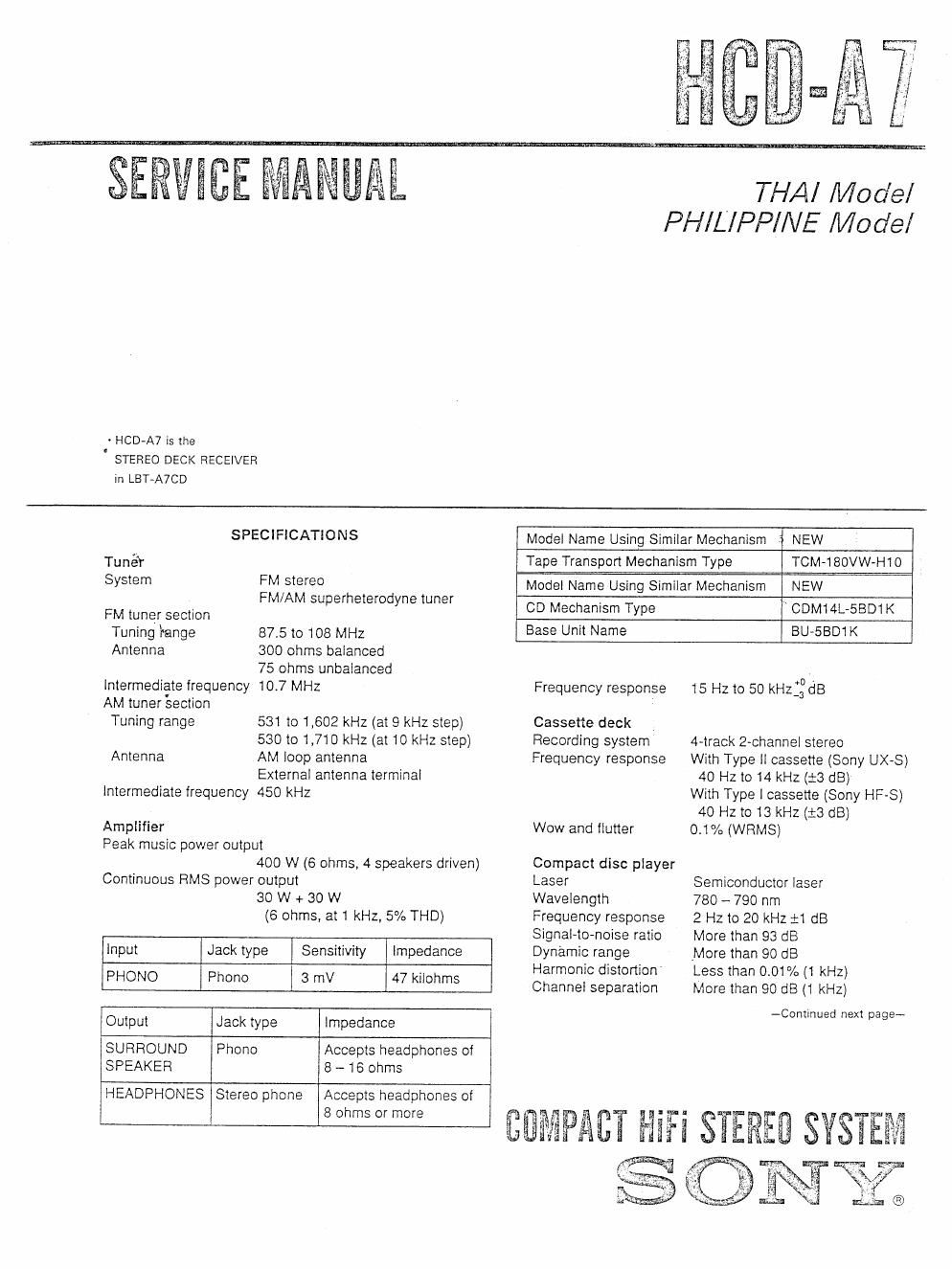
THAI Model
PHILIPPINE Model

- HCD»A7 is the
' STEREO DECK RECEIVER

in LBT~A7CD

SPECIFICATIONS Model Name Using Similar Mechanism NEW
Tuner Tape Transport Mechanism Type TCM-i80VW-H10
System FM SIEIGO Model Name Using Similar Mechanism NEW
. FM/AM suljerheemdyne Une CD Mechanism Type CDM14L-SBD1 K

FM tuner section .

Tuning range 87.5 to 108 MHz Base 7" Name BU5BD1 K

Antenna 300 ohms balanced

75 ohms unbalanced
Intermediate frequency 10.7 MHz
AM tuner section

Tuning range 531 to 1,602 kHz (at 9 kHz step)
530 to 1,710 kHz (at 10 kHz step)
Antenna AM loop antenna

External antenna terminal
Intermediate frequency 450 kHz

Amplifier
Peak music power output
400 W (6 ohms, 4 speakers driven)
Continuous RMS power output
30 W + 30 W
(6 ohms, at 1 kHz, 5% THD)

Input Jack type Sensitivity Impedance
PHONO Phone 3 mV 47 kilohms
Output Jack type impedance
SURROUND Phono Accepts headphones of
SPEAKER 8 ~16 ohms

HEADPHONES Stereo phone Accepts headphones of
8 ohms or more

Frequency response 15 Hz to 50 kHZ:30 dB

Cassette deck
Recording system 4-track 2~channel stereo
Frequency response With Type II cassette (Sony UX-S)
40 Hz to 14 kHz (:3 dB)
With Type 1 cassette (Sony HF-S)
40 Hz to 13 kHz (:3 dB)

Wow and flutter 01% (WRMS)
Compact disc player

Laser Semiconductor laser
Wavelength 780 - 790 nm

Frequency response 2 Hz to 20 kHz :1 dB
Signal-to-noise ratio More than 93 dB
Dynamic range More than 90 dB
Harmonic distortion Less than 0.01% (1 kHz)
Channel separation More than 90 dB (1 kHz)

-Continued next page-

Page 2

4.1%

General

Power requirements 220 - 230 V AC, 50/50 Hz

Power consumption 90 W

Mass Approx. 8.6 kg

Dimensions Approx. 355 x 380 x 325 mm
(w/h/d, including projections)

Accessories supplied

Remote commander (1)

Batteries Sony SUM-3 (NS) (2)
(except for Thai models)

FM wire antenna (1)

AM loop antenna (1)

Design and specifications are subject to change without
notice.

To prevent Ilte or shock hazard, do not expose the unit to
rain or moisture.

To avoid electrical shock, do not open the cabinet. Fleier
servicing to qualified personnel only.

This appliance is classified as a CLASS 1 LASER product.

The CLASS 1 LASER PRODUCT MARKING is located on
the rear exterior.

CLASS 1 USER PRODUCT
LUOKAN 1 LASERLAITE

xuss 1 MSERAPPAFIAT
, '

Laser component in this product is capable oi emitting
radiation exceeding the limit for Class 1.

The following caution label is located inside the unit.

wow-ii m
t CAUTION
55 4 usqu ussnsrmnc van Ammo NA: '
ADI/AR WRNEDW ane summon.
uocA ms mass was s
| - AVATTAE$SAJA WITUS a-nEi-r U
VARD' ' an ALI'YIINA KATEILYUE. E55"

LL§F$TRMJNG NAN WA WAD
VARNING ' 001 SPMREN AR mom? M '

- ; usEnstmm tun DEKSEL Am:
ADVARS=L Wmmem FOR swim. s
tW'wIM-W' . w , .

TABLE OF CONTENTS

Section m Page

'i. DiAGRAMS
1-1. Printed Wiring Boards-Main Section- WW4
1'2. Schematic Diagram-Main Section- -------------- 7
1-3. Printed wiring Board-Pancl Section- """"""" 10
1-4, Schematic Diagram-'Pancl Section~ ------------- 13
1-5. Printed wiring BoardSWTC Section- W16
1-6. Schematic Diagram-TC Scctionv 19
H. Printed wiring Boards-CD Section- ............ 21
1-8. Schematic Diagram-CD section- .................. 23
1-9. Schematic Diagram-Tuner Scction-~ ------------ 26

2. EXPLODED VIEWS

2-1. Cabinet Section


Z-Zt Front Panel Section
2-3. Mechanism Deck Section-l

2-4. Mechanism Deck Section-2

2-5. Mechanism Deck Section»3 ------------------------------ 32
2-6. CD Mechanism Section --------------------------------- 33
2-7. Optical Pick-up Block Section 34
3. ELECTRICAL PARTS LIST ~~~~~~~~~~~~~~~~~~~~~~~~~~~~ 35

SAFETY-RELATED COMPONENT WARNINGII

COMPONENTS IDENTIFIED BY MARK A OR DOTTED
LINE WITH MARK A ON THE SCHEMATIC DIAGRAMS
AND IN THE PARTS LIST ARE CRITICAL TO SAFE
OPERATION. REPLACE THESE COMPONENTS WITH
SONY PARTS WHOSE PART NUMBERS APPEAR AS
SHOWN IN THIS MANUAL OR IN SUPPLEMENTS PUB-
LISHED BY SONY.